
Install Manual

Preliminary
SKY899
Installation Manual
2-21
Rev. A
2.7 AIRCRAFT DISCRETE INPUTS
The aircraft discrete inputs are used to assist in determining the aircraft's phase of flight or flight
condition (e.g., on ground or in flight). Inputs are diode isolated inside the TRC, do not install isolation
diodes externally. The active or inactive state of the inputs can be high or low, they will be saved in the
System Configuration Module during system setup using the service menu.
2.7.1 Audio Inhibit (Terrain Warning System - GPWS)
The audio inhibit input will sense a terrain warning alarm (i.e., GPWS, EGPWS, TAWS) and temporarily
disable the audio alert output until the terrain warning clears. The input can be either a constant flag
signal or an alternating flag output. The flag must be cleared for 5 seconds before the TRC accepts a “NO
ALARM” condition and restores audible alerts.
NOTES
1. If the aircraft is equipped with terrain warning system, it must be connected
to the TRC.
2. If the aircraft is not equipped with terrain warning system, leave this input
unconnected.
Audio inhibit connection:
GPWS P1-34
2.7.2 Landing Gear
This input is to be connected to the landing gear switch to sense the position of the landing gear (fixed, up
or down). The switch status of this input is selected during system setup via the service menu. This input
has three service menu options, none (fixed gear), active low (electrically ground with aircraft on the
ground) and active high (electrically high (+9 V to +28 V) with aircraft on the ground).
Landing gear connection:
GEAR P1-33
If the aircraft does not have a landing gear switch (e.g., fixed-gear aircraft), leave this input unconnected.
With this configuration, if a radio altimeter (analog or ARINC-429) is not installed, the system will default
to the highest TA sensitivity level (level B) and audio TA announcements (i.e., “traffic, traffic”) will not be
inhibited during takeoff and landing.
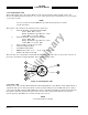
2.7.3 SKYWATCH/
Stormscope
Mode Switch
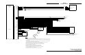
The SKYWATCH/Stormscope mode switch (SW1) is required only if a WX-1000 Stormscope Weather
Mapping System is installed. This switch permits the flight crew to switch the display between the
SKY899 and WX-1000. If a TA (Traffic Advisory) is detected while in the Stormscope mode, the display will
switch to the SKYWATCH mode. Refer to figure 2-3 for interconnect wiring information. Any general
purpose SPST toggle switch (3 Amp @ 28 V dc) may be used. Display mode switch cable routing and length
are not critical to system operation. Mount the switch at a location easily accessible to the pilot.
SKYWATCH/Stormscope mode switch connections:
SMS P1-15
SMS_RET P1-23
2.7.4 Squat Switch (Weight-On-Wheels)
This input is to be connected to the squat switch (weight-on-wheels) to sense when the aircraft is on the
ground. The switch status of this input is selected during system setup via the service menu. This input
has three service menu options, none (no squat switch installed), active low (electrically ground with
aircraft on the ground) and active high (electrically high (+9 V to +28 V) with aircraft on the ground).