
Install Manual

Preliminary
SKY899
Installation Manual
2-20
Rev. A
7
6
5
1
11
3
2
4
10
9
8
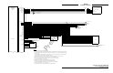
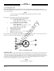
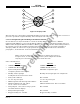
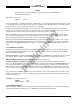
Figure 2-6. Display Cable
The sub-cable color-coded jackets and shields should be left on the sub-cables as close to the connectors as
practical to provide the required shielding and to identify the sub-cables.
2.6.8 Converting Existing Aircraft Wiring from SKY497 to SKY899
In some instances, it may be desirable to convert an existing SKY497 installation to a SKY899
installation. The SKY899 is a new system with the addition of a system configuration module and a new
TRC899. Even though the TRC899 resembles a TRC497, uses the same antenna and mounting hardware,
the external connector P1 has different pinouts and is keyed differently to prevent the possibility of
damaging a TRC. In order to relocate pin positions use the insertion and extraction tools listed in
paragraph 1.7, under sub title "Connector Installation."
NOTE
All P1 connections will need to be moved from an existing pin location to a
new pin location, as well as the addition of the system configuration module.
Only the power and antenna connections remain the same.
Some of the differences:
TRC899
TRC497
• 7 ARINC-429 RX channels
2 ARINC-429 RX channels
• 3 ARINC-429 TX channels
1 ARINC-429 TX channel
• System Configuration Module
(configure system in service menu)
Individual configuration pins
• Heading valid, 1 input pin
(low/high level selected in service menu)
Heading valid, 2 input pins (low or high level)
• Analog radio altimeter
Not available
• 18 - 32 V dc power input
11 - 34 V dc power input
• ADS-B (requires mode S transponder address)
Not available
• Altimeter Gilham Code "D2" added
(do not connect if not available)
Altimeter Gilham Code "D2" not available
• Lamp Outputs - above, below and oper_mode
(used with alternate display)
Not available
• Transponder input/output
Not available
• Stepper (heading) not available
Stepper (heading) available