
Install Manual

Preliminary
SKY899
Installation Manual
2-19
Rev. A
2.6.6 Suppression Bus Cable
For the suppression bus use any size low capacitance shielded cable. Cable runs should be as short as
practicable and the shields should be grounded at both ends.
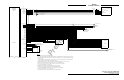
2.6.7 WX-1000/SKY497 Display and WX-1000 Processor Cable
The display cable connects the TRC to the WX-1000/SKY497 Display. Cable specifications are listed below
(see paragraph 1.7 for cable vendors). If a WX-1000 Stormscope® Weather Mapping System is installed,
the same cable is used to connect the TRC to a WX-1000 processor. Refer to figure 2-2 (without WX-1000
processor) or 2-3 (with WX-1000 processor) for interconnect wiring information. Pin-out information
relating to the WX-1000 display and processor is also provided in tables 2-2 and 2-3.
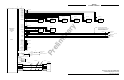
For alternate display device cable see ARINC-429 data cable (par. 2.6.3) and refer to figure 2-4 for
connections.
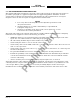
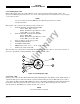
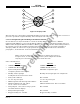
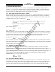
The display cable consists of the following (refer to figure 2-6).
1. Twisted, shielded, jacketed triad #22 AWG
Colors: White, Blue, Orange
Shield: Tin plated copper braid, 90% min.
Jacket: FEP .007 in. min., White jacket
2. Twisted, shielded, jacketed pair #24 AWG
Colors: White, Blue
Shield: Tin plated copper braid, 90% min.
Jacket: FEP .007 in. min., Blue jacket
3. Same as 2 except Orange jacket.
4. Same as 2 except Green jacket.
5. Same as 2 except Red jacket.
6. Same as 2 except Black jacket.
7. Same as 2 except Yellow jacket.
8. Aluminized Mylar
®
wrap.
9. #34 AWG braided shield.
10. FEP Teflon
®
jacket .013 in. - .023 in., Red tint.
11. Marker tape with Vendor P/N.