
Install Manual

Preliminary
SKY899
Installation Manual
2-18
Rev. A
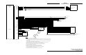
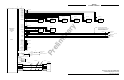
2.6.4 Heading Input Cable
The heading input cable connects the TRC899 to the aircraft synchro heading system (refer to the
Interconnect Wiring Diagram, figure 2-2, 2-3 or 2-4). Cable specifications are listed below (see paragraph
1.7 for cable vendors).
NOTE
Use of any cable not meeting BFG Avionics Systems specifications voids all
system warranties.
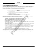
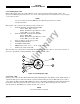
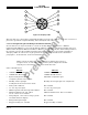
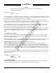
The synchro cable consists of the following (refer to figure 2-5):
1. Twisted, Shielded, Jacketed Triad #24 AWG
Colors: White, Blue, Orange
Shield: Tin Plated Copper Braid, 90% min.
Jacket: FEP .007 in. min., White
2. Twisted, Shielded, Jacketed Pair #24 AWG
Colors: White, Blue
Shield: Tin Plated Copper Braid, 90% min.
Jacket: FEP .007 in. min., Blue
3. Same as Item 2, except Orange jacket.
4. Aluminized Mylar
®
Wrap.
5. #34 AWG braided shield.
6. FEP Teflon
®
jacket .013 in. - .023 in., clear (translucent).
7. Marker tape with vendor P/N.
The sub-cable color-coded jackets and shields should be left on the sub-cables as close to the connector as
practical to provide the required shielding and to identify the sub-cables.
1
2
7
6
5
4
3
Figure 2-5. Heading Input Cable
2.6.5 Power Cable
For the power cable, use #16 AWG (minimum) twisted shielded pair cable (Beldon 83322, Alpha 2826/2, or
equivalent). The power cable runs from the aircraft circuit breaker panel to the TRC. The power cable is
connected to the TRC using the MS3126F12-3S connector included in the TRC installation kit. Terminate
the shield to airframe ground at the power source. Power cable routing and length are not critical to
system operation. The SKY899 is a 28 V dc system (18 to 32 V dc).
NOTE
5 A circuit breaker is required.