
Install Manual

Preliminary
SKY899
Installation Manual
2-17
Rev. A
2.6.1 Antenna Cables
NOTES
1. Use of any cable not meeting BFGoodrich Avionics Systems specifications
voids all system warranties.
2. If you fabricate your own cables, you must verify that the attenuation and
VSWR does not exceed the specified values.
3. To add strain relief and alleviate stress caused by aircraft vibration, place 4-
6 inches (10.2 to 15.2 cm) of heat shrink tubing over each antenna connector
and cable.
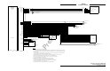
The directional antenna requires three cable assemblies; sum (Sigma Port), bit probe (Probe Port) and
difference (Delta Port). Cable attenuation for the sum and difference ports must not exceed 2.5 dB.
Attenuation for the bit probe cable must not exceed 6 dB. VSWR, on cables attached to the sum, bit probe,
and difference ports, must not exceed 1.5:1. (See paragraph 1.7 for antenna cable vendors and
specifications.)
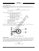
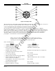
At the antenna, each connector has an identifying color band. To ensure the cables are connected to the
correct port, affix the following marking at the termination points of each cable:
Sum (Sigma) Port The Sum (Sigma) port is the forward antenna connector. It is marked with
a blue band. Fabricate the sum antenna cable with a TNC connector at
each end. Affix a blue marking band on each connector. At the TRC, the
sum port (J9) is identified with blue marking.
Bit Probe Port The Bit Probe port is the center antenna connector. Fabricate the probe
cable with a BNC connector at each end.
Difference (Delta) Port The Difference (Delta) port is the rear antenna connector. It is marked with
a red band. Fabricate the difference antenna cable with a TNC connector at
each end. Affix red marking band on each connector. At the TRC, the
difference port (J11) is identified with red marking.
When routing antenna cables, observe the following precautions:
• All cable routing should be kept as short (do not exceed maximum cable length detailed in table 1-
6) and direct as possible.
• Avoid sharp bends (do not exceed maximum bend radius detailed in table 1-6).
• Avoid routing cable near power sources (e.g., 400 Hz generators, trim motors, etc.) and near power
for fluorescent lighting.
• Avoid routing cable near ADF antenna cable (allow at least a 12-inch (30.5) separation).
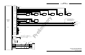
2.6.2 Audio Output Cable
For audio output cable use #22 AWG (minimum) twisted shielded pairs with the shield grounded at both
ends. Cable runs can be up to 30 ft., but should be as short as practicable.
2.6.3 Data Cables
RS-232, RS-422, and ARINC-429 data cables are #22 AWG (minimum) twisted, shielded cables. The shield
shall be grounded at both ends and at all breaks. Cable runs should be as short as practicable.