
Install Manual

Preliminary
SKY899
Installation Manual
2-16
Rev. A
2.6 CABLE REQUIREMENTS AND FABRICATION
The installer will supply and fabricate all system cables. Cable specifications and approved vendors are
provided in paragraph 1.7, equipment required but not supplied. Appendix A defines the electrical
characteristics of all input and output signals and identifies the cable requirements for each signal.
Required connectors and contact pins are supplied in the installation kits.
NOTES
1. Use of any cable not meeting BFG Avionics Systems specifications voids
all system warranties.
2. All wiring must be in accordance with industry accepted methods,
techniques and practices.
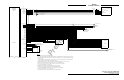
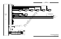
3. All wires are 22 AWG. except where noted, refer to figures 2-2, 2-3 and
2-4 for interconnect wiring information.
The length and routing of the external cables must be carefully studied and planned before attempting
installation of the equipment. Observe the following precautions:
• ARINC-429 inputs (receive channels) must be paired with other ARINC-429 inputs of the same
speed (12.5 or 100 kHz). Details are outlined in paragraph 2.9.
• All cable routing should be kept as short and direct as possible.
• Avoid routing the cables too close to aircraft control cables.
• Avoid routing cable near the ADF, comm radio, or transponder antenna cables (allow at least a 12
inch (30.5 cm) separation).
• Avoid routing cable near power sources (e.g., 400 Hz generators, trim motors, etc.) and near power
for fluorescent lighting.
• Use pressurized bulkhead connectors certified for your specific aircraft pressurization.
• To limit the possibility of wire chafing, it is recommended that heat shrink sleeving be installed
over the wire bundle between the shield termination’s (inside the connector backshell) and the
connector cable clamp.
• Observe all wiring notes on interconnect wiring diagram (figures 2-2, 2-3 and 2-4).
After fabricating the cables and before installing the equipment, use the interconnect diagram to verify
continuity between each pin and its opposite end termination. Check resistance to ground between each
connector pin. When a path to ground is detected, verify its validity. Figure A-1 P1 connector pin
identifiers has been added to assist in fabrication and continuity verification of the interconnect cable.