
Install Manual

Preliminary
SKY899
Installation Manual
2-15
Rev. A
2.5 DISPLAY LOCATION
The display should be mounted in a location easily accessible and clearly visible to the pilot. If using an
alternate display device refer to manufacturer instructions for location. In selecting a location for WX-
1000/SKY497 display, consider the following:
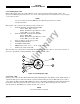
Magnetic Effect Where possible to avoid it, the display should not be mounted within
3 inches (8 cm) of an electric turn and bank indicator, as the magnetic
effect of the turn and bank motor may affect the display presentation. (A
common symptom of magnetic interference is a wobbling or vibrating
display raster.)
NOTE
If it is necessary to mount the display unit next to a device that may affect
the CRT display, magnetic shielding material can be placed around the
display unit. Shielding material is available from BFG Avionics Systems.
Specify P/N 78-8060-5882-8 when ordering.
Panel Depth Adequate depth must be available behind the instrument panel to allow for
the display, the display connector, and excess display cable. Remember
that a service loop is necessary to allow access to the display connector
when removing the display or inserting it into the instrument panel.
Cooling While the display has no special cooling requirements, it should be
mounted to permit adequate ventilation.
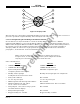
Viewing Angle The viewing angle for the CRT display is not a critical factor. The most
favorable mounting position would be near eye level and no more than
arms length from the principle user of the instrument.