
Install Manual


Preliminary
SKY899
Installation Manual
1-21
Rev. A
Miscellaneous Hardware
The installer must provide suitable hardware to attach the TRC Mounting
Tray. The following stainless steel fasteners are recommended:
Channel Mount: Four 8-32 UNC-2A pan head machine screws per
ANSI B18.6.3. (Six are required for the ruggedized
tray.)
or
Four 8-32 UNC-2A hex socket cap machine screws
per ANSI/ASME B18.3. (Six are required for the
ruggedized tray.)
Four No. 8 helical spring lockwasher per
ANSI/ASME B18.21.1. (Six are required for the
ruggedized tray.)
Flat Mount Eight 6-32 UNC-2A 100 degree flat head machine
screws per B18.6.3.
Oscilloscope
Required to verify SKY899 suppression pulse (100 µs ±5µs, +28 V dc).
Power Cable For the power cable, use #16 AWG (minimum) twisted shielded pair cable
(Beldon 83322, Alpha 2826/2, or equivalent).
RS-232 Terminal Device
(e.g., Laptop Computer)
Required if using an alternate display, (see Appendix E for instructions).
Terminal device is used for system setup, post installation checkout and
troubleshooting. Any computer, with RS-232 terminal emulation software
(e.g., Procomm®, HyperTerminal, etc.) may be used as the terminal device.
A standard 9-pin serial cable is required.
Surface Preparation Alodine® No. 1001 required for installation of the antenna.
Switches If an alternate display is used a separate ON/OFF switch is required. Any
general purpose SPDT toggle switch (3 A @ 28 V dc) may be used.
If the final configuration includes a WX-1000 Stormscope Weather Mapping
System, two external switches will be required. A SPST switch will be
required for the SKYWATCH/Stormscope display mode switch (SW1). A
DPDT switch will be required for the WX-1000 maintenance switch (SW2).
Any general purpose toggle switch (3 A @ 28 V dc) may be used.
WX-1000/SKY497 Display &
WX-1000 Processor Cable
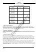
This cable is used to connect the WX-1000/SKY497 display and/or WX-1000
processor to the TRC. Required connectors and contact pins are supplied in
the installation kit. Cable specifications and U.S. vendors are listed below
in table 1-11.
NOTE
Use of any cable not meeting BFG Avionics Systems specifications voids all
system warranties.