
Install Manual

Preliminary
SKY899
Installation Manual
1-20
Rev. A
Connector Installation
(Continued)
P8 Power Crimping Tool M22520/1-01
Positioner M22520/1-02
Insertion MS24256A16
Removal MS24356R16
P101 Display Crimping Tool M22520/2-01
Positioner M22520/2-08
Insertion/Removal M81969/1-02
Data Cables RS-232, RS-422, and ARINC-429 data cables are #22 AWG (minimum)
twisted, shielded cables.
Flightline Tester Either the BFG TT391 Flightline Tester, IFR Systems TCAS-201 (with
TCAS I firmware) Ramp Test Set (Appendix C), or TIC T-49C Flightline
Tester (Appendix D). The test set is required to do the post installation
checkout.
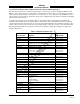
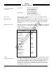
Heading Input Cable This cable provides aircraft heading information to the SKY899. Cable that
meets the specification for SKY899 installation is available from suppliers
listed in table 1-10.
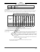
Table 1-10. Heading Input Cable Vendors
US
COMPANY
CABLE
P/N
Dallas Avionics
1-800-527-2581
214-320-9776
FAX 214-320-1057
Electronic Cable
Specialists
1-800-327-9473
414-421-5300
FAX 414-521-5301
A.E. Petsche
817-461-9473
FAX 817-277-2887
EDMO Distributors
1-800-235-3300
805-295-6689
FAX 1-800-828-0623
FAX 805-295-6703
PIC Wire and Cable
1-800-742-3191
262-246-0500
FAX 262-246-0450
WX-5
(6.84 lb/
100 ft)
3N6607
(7.5 lb/
100 ft)
TZGYR
(6.84 lb/
100 ft)
WX-1000
SYNCHRO
WM25807
(7.2 lb/
100 ft)
Lamps
(external annunciators)
External annunciators are required when using an alternate display that is
not capable of displaying above and below vertical modes. Lamp outputs
are switched to ground when active (LP1OUT & LP2OUT). Lamps should
be labeled ABV and BLW. An optional operation mode lamp can be
installed to show system has been switched from standby into operation
mode. Refer to paragraph 2.14, 2.15 and A.2. Lamps can be 12V or 28V
with maximum current 300 mA