
Install Manual

Preliminary
SKY899
Installation Manual
1-17
Rev. A
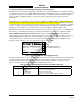
Table 1-6. TRC899 Software Revisions
SYSTEM
REVISION
SKY HP
VERSION
DESCRIPTION
1.00 1.00 Original production release.
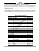
1.6 INTERFACE
The electrical characteristics of all input and output signals are detailed in Appendix A. Listed below in
table 1-7 is the minimum equipment required to interface with the SKY899. See chapter 2 for details.
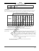
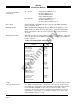
Table 1-7. Minimum Interface Equipment Required
AVIONICS EQUIPMENT
SURVEILLANCE
MODE
MAGNETIC HEADING
BAROMETRIC ALTITUDE
RADIO ALTITUDE
GPS NAV
LANDING GEAR SWITCH
SQUAT SWITCH (WOW)
SUPPRESSION BUS
AUDIO INHIBIT (GPWS)
EXTERNAL LAMPS
PILOT CONTROLS
(PUSHBUTTONS)
AUDIO SYSTEMS
ATCRBS
(Active Only)
①
X
①①
XX
②③ ③
X
ATCRBS & ADS-B X X
①
X
①
XX
②③ ③
X
X
Required.
① Optional but will enhance performance. (See paragraphs 2.7 thru 2.23 for details.)
② Required if Terrain Warning System (GPWS) is installed.
③ Only if Alternate Display requires it, see display manufacturer's instructions.
1.7 EQUIPMENT REQUIRED BUT NOT SUPPLIED
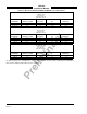
Antenna Cables The installer will supply all antenna cables and connectors. The directional
antenna requires three cable assemblies; sum (Sigma Port), bit probe
(Probe Port) and difference (Delta Port). Cable attenuation for the sum and
difference ports must not exceed 2.5 dB. Table 1-8 identifies U. S. vendors
who sell approved cables by the foot. Table 1-9 provides a cable to connector
cross-reference.
RG142B or equivalent may be used for the bit probe cable. Attenuation for
the bit probe cable must not exceed 6 dB.
NOTE
Use of any cable not meeting BFGoodrich Avionics Systems specifications
voids all system warranties.