
Install Manual

Preliminary
SKY899
Installation Manual
1-6
Rev. A
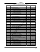
The following table identifies the components which make-up the SKY899 system.
Table 1-1. SKY899 System
COMPONENT PART NUMBER
TRC899 Transmitter Receiver Computer 805-11900-001
System Configuration Module 814-18005-001*
WX-1000/SKY497 Display (Optional) 78-8060-5900-x**
Directional Antenna
NY156 805-10003-001
NY164 805-10890-001
* System Configuration Module is included in the installation kit P/N 817-11900-xxx (see table 1-2).
** Dash numbers identify different versions (refer to para 1.4.2).
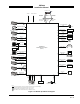
1.3.1 TRC899 Transmitter Receiver Computer P/N 805-11900-xxx
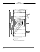
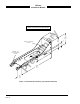
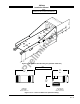
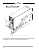
The TRC is mounted in a mounting tray supplied with the installation kit (see table 1-2). The standard
tray (figure 1-3) will meet the requirements for fixed wing aircraft. A ruggedized version of the tray (figure
1-4) is required for rotorcraft installations.
To meet different space requirements, the I/O signal connector (P1) will accommodate either a straight or
right-angle backshell. TRC installation kits (see table 1-2) include either a straight backshell or right-angle
backshell (see figure 1-5).