
Install Manual

Preliminary
SKY899
Installation Manual
F-4
Rev. A
h. Set the SELF-TEST switch to the 1030 position and verify that the 1030 indicator blinks on for
1/2 second every 5 seconds.
i. Set the SELF-TEST switch to the 1090 position and verify that the 1090 indicator blinks on for
1/2 second every 5 seconds.
j. Set SELF-TEST switch to center position (off). Set the POWER switch to the OFF position.
NOTE
Care should be taken to ensure that the Patch Antenna is connected to TT391
connector J1 and NOT J2. IF THE PATCH ANTENNA IS CONNECTED TO
J2 THE TT391 WILL NOT FUNCTION CORRECTLY.
k. Connect the Flightline Tester coax cable to J3 on the Patch Antenna and to connector J1 in the
chassis. (J2 should remain capped by the dust cover).
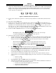
Figure F-3. Typical Patch Antenna Tripod Mount
22. From each test point (see step 13):
a. Position the TT391 Patch Antenna facing the SKYWATCH HP aircraft under test.
b. Set the TT391 POWER switch to the ON position.
c. Verify that the display shows, in the direction (± 30 degrees) of the TT391, two targets; a Traffic
Advisory (i.e., a solid circle) at ¼ nm and Other Traffic (i.e., open diamond) at 4.5 nm. Both
targets will be displayed in level flight at own aircraft altitude (i.e., "00" displayed above the
traffic symbol).
NOTES
1. If the display reflects a gross error in target bearing, check the directional
antenna cables at TRC connectors J9 (sum port) and J11 (difference port).
They may be reversed. A further indication of this condition would be a
target that moved in a counter-clockwise direction when the TT391 is
moved in a clockwise direction.
2. Multiple targets or a faulty bearing may result from multipath distortion
(see step 1).
3. During these tests, the SKY899 may detect and display other active
targets.
4. To obtain a better line of sight, it may be necessary to elevate the patch
antenna.
d. Set the TT391 POWER switch to the OFF. Repeat procedure from each test point. Step 16 can
be done from the last test point.