
Install Manual

Preliminary
SKY899
Installation Manual
F-3
Rev. A
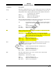
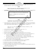
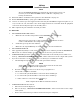
16. Change the altitude display modes from normal (NRM), below (BLW), above (ABV), and unrestricted
(UNR). Verify that the system toggles through the altitude display modes correctly (some alternate
displays do not support unrestricted display mode). If external annunciators are connected verify
correct operation (see figure F-2).
ABV BLW
(Above)
ABV BLW
(Below)
ABV BLW
(Normal)
ABV BLW
(Unrestricted)
Figure F-2. External Annunciator Operation.
17. If oper_mode annunciator (optional) is connected, verify annunciator works when system is turned
ON.
18. Select the normal (NRM) mode.
19. Position the aircraft with the nose aligned on any 90 degree heading. Avoid areas within 250 ft of
obstructions (e.g., hangers, large aircraft, control towers, etc.) where there is a potential for multipath
problems. Locate and mark test points at 30 degree intervals (i.e., 000, 030, 060, 090, 120, 150, 180,
210, 240, 270, 300, and 330 degrees) with respect to the directional antenna. Mark these points at the
same distance, between 100 and 150 ft, from the aircraft.
20. Position the TT391 Flightline Tester on one of the test points identified above.
CAUTION
The Flightline Tester is not weatherproof when the lid is open. Do not setup
or operate the Flightline Tester in conditions of rain, sleet, etc.
21. Setup and verify operation of the TT391 Flightline Tester:
a. Open the chassis lid and remove the lid from the chassis by sliding the lid off of the hinge pins
(sliding it to the right). The lid "stay" must be removed from the lid before mounting. The stay
will pop off of the lid. (The stay is the hinged part that props the lid open on the chassis).
NOTE
The Patch Antenna may be used without a tripod. The Patch Antenna can be
held, or secured, and pointed towards the SKYWATCH HP aircraft under test
WITH THE MOUNTING STUD POINT TOWARD THE GROUND. This orientation is
critical.
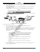
b. Mount the chassis lid, with the Patch Antenna facing the aircraft, onto a tripod (not included).
The tripod must be capable of holding the antenna (approximately 2.5 lb.) and must provide a
standard base mounting stud threaded 1/4"-20. A typical tripod mount is shown in figure F-3.
c. If the internal batteries are being utilized, proceed to sub-step f. If the Flightline Tester AC
Converter Power Supply is to be utilized, proceed to sub-step d.
d. Connect the AC Converter Power Supply cable connector to the chassis external connector.
e. Connect the AC Converter Power Supply input power cable connector to one of the following AC
sources:
• 115 V ac, 60 Hz
• 115 V ac, 400 Hz
f. Set the Flightline Tester POWER switch to the ON position.
g. Verify that the LOW indicator is not steady on (it may flash). If the LOW indicator remains on
(i.e., lit), perform one of the following three options:
• Use the AC Converter Power Supply to power the unit.
• Recharge the internal batteries.
• Replace the internal batteries.