
Install Manual

Preliminary
SKY899
Installation Manual
F-1
Rev. A
APPENDIX F
Installation Checkout Using
an Alternate Display
F.1 INTRODUCTION
This section contains installation checkout procedures for the BFGoodrich Avionics Systems
SKYWATCH
®
HP SKY899 that is interfaced to an alternate display (e.g., EFIS, IVSI, BFGoodrich Avionics
Systems RGC250, MFD).
NOTES
1. This section provides checkout information for the SKY899 interfaced to an
Alternate Display.
2. When interfacing to BFG Avionics Systems RGC250, software version for
RGC250 must be 1.5 or higher.
3. This procedure assumes familiarity with the set up and operation of the TT391
Flightline Tester and RS-232 terminal device (see Appendix E). If using
another approved tester refer to the appropriate appendices for test procedure.
4. All test equipment used in completing these tests shall be calibrated in
accordance with the manufacturer's recommendations.
This procedure will validate the installation and return to service of the BFGoodrich Avionics Systems
SKY899.
F.2 CONTROLS
Operating instructions for each alternate display are provided with the display manufacturer's
documentation.
NOTE
When using an alternate display all SKY899 functions are controlled through
the alternate display. Each alternate display will show information consistent
with the capabilities of that particular display. Therefore, the text displayed
may be different from what is called out in this procedure. Reference the
alternate display documentation for appropriate screen text.
F.3 CHECKOUT PROCEDURE
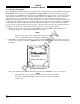
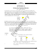
The TT391 Flightline Tester simulates both a ground based secondary surveillance radar (SSR) and an
airborne transponder. With the SKY899 set to GROUND TEST (i.e., the barometric altimeter is simulated
to 50,000 ft, heading simulated to 0 degrees, and the radar altimeter simulated to 2,500 ft) the TT391 will
simulate two targets; a Traffic Advisory (i.e., a solid circle) at ¼ nm and Other Traffic (i.e., open diamond)
at 4.5 nm. Both targets will be displayed in level flight at own aircraft altitude (i.e., "00" displayed above
the traffic symbol).
If the indications given in the following procedure, except for the Flightline Tester, are not obtained, refer
to the troubleshooting procedures in Chapter 4. If indications given for the Flightline Tester are not
obtained, refer to the maintenance section of the TT391 Instruction Manual.
1. Connect the RS-232 terminal device to J7 TEST port on the TRC899. Turn ON and setup the terminal
device. (See Appendix E for terminal device commands, setup, and operating instructions.)