
Install Manual


Preliminary
SKY899
Installation Manual
D-3
Rev. A
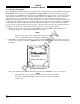
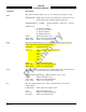
BRT
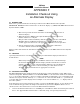
OFF
OPRMSG
Standby
SKY899
TEST
Figure D-3. Standby Screen
3. Perform System Setup in paragraph 3.3.1. (If System Setup has already been done, proceed to next
step.)
4. Turn SKY899 OFF and then enter the Service Menu (see paragraph 4.4) by holding the left two
buttons (soft-keys 1 and 2) depressed as the system is turned ON.
5. From the Service Menu, calibrate the TRC to the directional antenna (see paragraph 4.4.3). If
calibration was just done during System Setup (see paragraph 3.3.1) proceed to next step.
6. Return to the Service Menu and select Information.
7. From the Information menu, select Data Monitor. The Data Monitors menu will appear.
8. Select each of the data monitors and verify the sensor information is correct (see paragraph 4.4.2.3):
a. Change the status of the landing gear, squat switch, altitude, and heading
sensors. Verify data monitors show the correct input changes (i.e., sensing of these
signals).
b. If the information is not correct, the sensor has failed to communicate with the TRC. Check
operation of the sensor and connections between the TRC and sensor.
c. Select exit until you return to the Service Menu.
9. Exit the Service Menu. Verify that the display shows the standby screen (figure D-3) and then press
Soft-key (4), labeled OPR.
10. Verify operation of range function. Soft-key (3) is labeled to indicate the current range. Press Soft-key
(3) to toggle the display range between 2, 6 and 15 nm.
11. Select the 6 nautical mile range.
12. Verify that the system toggles through the altitude display modes. Soft-key (2) is labeled to indicate
the current mode. Press Soft-key (2) to select normal (NRM), below (BLW), and above (ABV).
13. Select the NRM (normal) mode.
14. If installed, turn the radio altimeter OFF.
15. Do the SKY899 self test (paragraph 3.4).
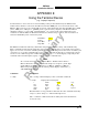
16. Position the aircraft with the nose aligned on any 90 degree heading. Avoid areas within 250 ft of
obstructions (e.g., hangers, large aircraft, control towers, etc.) where there is a potential for multipath
problems. Locate and mark test points at 30 degree intervals (i.e., 000, 030, 060, 090, 120, 150, 180,
210, 240, 270, 300, and 330 degrees) with respect to the SKY899 directional antenna. Mark these
points at the same distance, between 100 and 150 ft, from the aircraft.