
Install Manual

Preliminary
SKY899
Installation Manual
C-1
Rev. A
APPENDIX C
INSTALLATION CHECKOUT
USING THE TCAS-201 RAMP TEST SET
C.1 INTRODUCTION
This section contains instructions for using the TCAS-201 Ramp Test Set (with TCAS I firmware) to do
post-installation checkout of the BFG Avionics Systems SKYWATCH
®
HP SKY899. This procedure
provides test setup data for the TCAS-201 ramp test set, refer to manufacturers instructions for detailed
setup, operation and maintenance information.
NOTES
1. This procedure assumes familiarity with the set up and operation of the TCAS-
201 ramp test set.
2. All test equipment used in completing these tests shall be calibrated in
accordance with the manufacturer's recommendations.
3. When the SKY899 is interfaced to an alternate display, reference Appendix F
while performing this checkout procedure.
This procedure will validate the installation and return to service of the BFGoodrich Avionics Systems
SKY899.
C.2 CONTROLS
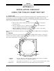
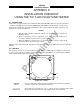
All operating controls are located on the front of the WX-1000/SKY497 display. Figure C-1 shows the
locations of the controls. Complete operating instructions for the SKY899 are provided in the SKY899
Pilot's Guide supplied with each system.
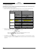
Figure C-1. Controls
OFF/BRT
Switch
Power is applied by rotating the knob clockwise past the detent. Continued
clockwise rotation increases display brightness.
1, 2, 3, & 4
Pushbuttons
Also referred to as soft-keys (1), (2), (3), and (4). In every operating mode a label
identifying the button function will be displayed next to the button.