
Install Manual

Preliminary
SKY899
Installation Manual
A-10
Rev. A
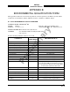
SIGNAL CHARACTERISTICS
Video Output Balanced video from the WX-1000 Processor (if installed) and output to
the display. Signal levels as specified in RS-422 specification.
CONNECTION Connector-Pin
Signal Name
P1-35 VIDEO_IN+ From Processor
P1-36 VIDEO_IN- From Processor
P1-16 VIDEO_OUT+ To Display
P1-17 VIDEO_OUT- To Display
CABLE See paragraph 2.6.7
VOLTAGE 0-5 V dc
CURRENT <100 mA
FREQUENCY <15 MHz
LOAD Z 1 kΩ
WX-1000/SKY497 Display Power supply to WX-1000/SKY497 display. +15/-15 V dc from the Display
Power WX-1000 Processor (if installed) and output to the display.
CONNECTION Connector-Pin
Signal Name
P1-25 DPWR+15_IN From Proc.
P1-26 DPWR-15_IN From Proc.
P1-27 DSPLY_GND_IN From Proc.
P1-8 DPWR+15_OUT To Display
P1-9 DPWR-15_OUT To Display
P1-10 DSPLY_GND_OUT To Display
CABLE See paragraph 2.6.7
VOLTAGE +15/-15 V dc
CURRENT 0.7 A input max.
Future Options The following connections are reserved for future use. THESE PINS
MUST REMAIN UNCONNECTED.
CONNECTION Connector-Pin
Signal Name
P1-1 +5 V
P1-3 -15 V
P1-32 DI02
P1-77 RS422_TXA
P1-78 RS422_TXB
P1-79 RS422_RXA
P1-80 RS422_RXB
P1-86 RS232_TX2
P1-87 RS232_RX2
P1-88 RX232_GND2