
Install Manual

Preliminary
SKY899
Installation Manual
A-9
Rev. A
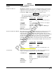
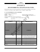
SIGNAL CHARACTERISTICS
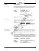
Suppression Bus I/O The SKY899 outputs a 100 µs (± 5 µs) suppression pulse on the aircraft
suppression bus (see paragraph 2.20). In addition, the SKY899 receives
suppression signals from all other devices on the suppression bus (e.g.,
transponder, DME). (Reference ARINC 735-2 and DO-197A.)
CAUTION
The aircraft transponder must have suppression circuitry to ensure
that SKYWATCH
HP does not paint itself as a target (e.g., TA).
CONNECTION Connector-Pin
Signal Name
P1-93 SUPBUS
CABLE Any size low capacitance shielded cable may be
used.
VOLTAGE 18 - 70 V dc input, greater than 20 V dc output.
CURRENT 0.3 A output max.
FREQUENCY ATCRBS - 100 µs ± 5 µs output
Mode S - 70 µs ±1 µs output DC-1 MHz input.
SOURCE Z 2 kΩ
LOAD Z 10.5 kΩ
MAX CAPACITANCE<50 pF
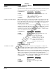
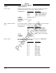
System Configuration Module The configuration module (i.e., personality plug) is used to store aircraft
installation dependent information. Aircraft specific information is
selected via the service menu, typically during system setup. Once the
setup settings have been saved the system configuration will stay with the
aircraft wiring allowing the TRC to be replaced or exchanged without
having to re-configure the TRC. When powered up the configuration
information is sent to the TRC via the bi-directional serial data bus (SDA).
The configuration module is located inside backshell of P1 connector. See
paragraph 2.21.
CONNECTION Connector-Pin
Signal Name
P1-2 3.3V
P1-92 PLUG_GND
P1-99 SDA
P1-100 SCL
CABLE Minimum 22 AWG wire for lengths up to 30 ft.
VOLTAGE ???????????????
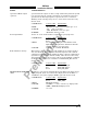
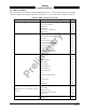
Vertical Sync Balanced vertical sync from the WX-1000 Processor (if installed) and
output to the display. Signal levels as specified in RS-422.
CONNECTION Connector-Pin
Signal Name
P1-30 VSYNC_IN+ From Processor
P1-41 VSYNC_IN- From Processor
P1-13 VSYNC_OUT+ To Display
P1-22 VSYNC_OUT- To Display
CABLE See paragraph 2.6.7
VOLTAGE 0-5 V dc
FREQUENCY 60 Hz
SOURCE Z 1 kΩ