
Install Manual

Preliminary
SKY899
Installation Manual
A-8
Rev. A
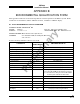
SIGNAL CHARACTERISTICS
Soft-keys Soft-key inputs from the WX-1000/SKY497 display and output to the
WX-1000 processor (if installed). The pushbuttons on the front of the
display are referred to as soft-keys (1), (2), (3), and (4). In every operating
mode a label identifying the button function is displayed next to the
button.
When using an alternate display device refer to manufacturer instructions
concerning these connections. Use of soft-key inputs will depend upon the
alternate display capabilities.
CONNECTION Connector-Pin
Signal Name
P1-18
SFTKEY1_IN
From Display
P1-19
SFTKEY2_IN
From Display
P1-20
SFTKEY3_IN
From Display
P1-21
SFTKEY4_IN
From Display
P1-37
SFTKEY1_OUT
To Processor
P1-38
SFTKEY2_OUT
To Processor
P1-39
SFTKEY3_OUT
To Processor
P1-40
SFTKEY3_OUT
To Processor
CABLE See paragraph 2.6.7
VOLTAGE Active: Min: 0.0 V
Max: 1.5 V
Inactive: Min: 3.5 V or Open
(Internal 4.7 kΩ pull-up)
Max: 5.0 V
Squat Switch Input This signal line is to be connected to the squat switch to sense when the
(Weight-On-Wheels) aircraft is on the ground (see paragraph 2.7.4). The state of the switch can
be active low or active high in reference to aircraft ground. The switch
status can be none, active low or active high, this is selected via service
menu.
If a squat switch is not installed on the aircraft, it is recommended to
install a switch, which will enhance system operation.
CONNECTION Connector-Pin
Signal Name
P1-24 SQUAT
CABLE Minimum 22 AWG wire for lengths up to 30 ft.
VOLTAGE None: Open or no connection
Active Low: (ref. to aircraft ground)
Valid: -5 V dc to +2.5 V dc
Invalid: +9 V dc to +32 V dc
Active High: (ref. to aircraft ground)
Valid: +9 V dc to +32 V dc
Invalid: -5 V dc to +2.5 V dc
CURRENT <5 mA sourced.