
Install Manual

Preliminary
SKY899
Installation Manual
A-7
Rev. A
SIGNAL CHARACTERISTICS
Operational Mode Output Operational mode output can drive a lamp annunciating when the system
(optional) is in operational mode. Output is switched to ground when system is in
operation mode. The lamp requires a separate dc source (constant or
dimming circuit). If lamp voltage is an ac source then an isolation relay
must be used.
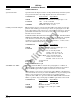
CONNECTION Connector-Pin
Signal Name
P1-31 OPER_MODE
CABLE Minimum 22 AWG wire for lengths up to 30 ft.
VOLTAGE ON: 0 V dc or Ground
OFF: Maximum +32 V dc or open
CURRENT Maximum current 300 mA.
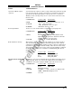
Power Input (TRC) 18-32 V dc. A 5 A circuit breaker is required (see paragraph 2.16).
CONNECTION Connector-Pin
Signal Name
P8-A +28V
P8-B +28V_RET
CABLE Use twisted shielded pair cable (Beldon 83322,
Alpha 2826/2, or equivalent). Terminate shield to
airframe at sensor or power source.
VOLTAGE 18 to 32 V dc, 70 Watts (Maximum)
Radio Altimeter (Analog) This interface allows a DC analog radio altimeter to be used to monitor
own aircraft height above ground and includes input for radio altitude
valid signal. Some analog radio altimeters utilize a discrete valid/invalid
signal line to indicate radio altitude validity, while others set the analog
data input line to a high out-of-range value for invalid altitude conditions.
If a discrete flag signal is not available leave RADIOALT_FLG (P1-14)
unconnected.
CONNECTION Connector-Pin
Signal Name
P1-6 RAD_ALT_IN_HI
P1-7 RAD_ALT_IN_LO
P1-14 RAD_ALT_FLG
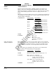
SKYWATCH/STORMSCOPE If a WX-1000 processor is installed, this signal (SW1 on the Interconnect
(SW1) wiring diagram, figure 2-3) switches the display between the WX-1000
and SKY899. Any general purpose SPST toggle switch can be used.
CONNECTION Connector-Pin
Signal Name
P1-15 SMS
P1-23 SMS_RET
CABLE Minimum 22 AWG.
VOLTAGE CLOSED (< 0.7 V dc) = Stormscope display mode
OPEN = SKYWATCH display mode.
CURRENT <100 mA