
Install Manual

Preliminary
SKY899
Installation Manual
A-6
Rev. A
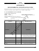
SIGNAL CHARACTERISTICS
Operational mode Operational mode output can drive a lamp annunciating when the system
is in operational mode. (See lamp outputs above for characteristics.)
CONNECTION Connector-Pin
Signal Name
P1-31 OPER_MODE
CABLE Minimum 22 AWG wire for lengths up to 30 ft.
VOLTAGE ON: 0 V dc or Ground
OFF: Maximum +32 V dc or open
CURRENT Maximum current 300 mA.
Landing Gear Switch Input This signal line is to be connected to the landing gear switch to sense the
position of the landing gear (fixed, up or down, see paragraph 2.7.2). The
state of the switch can be active low or active high in reference to aircraft
ground. The switch status can be fixed, active low or active high, this is
selected via service menu.
IF THE AIRCRAFT DOES NOT HAVE A LANDING GEAR SWITCH, THIS INPUT MUST
REMAIN UNCONNECTED
.
With this configuration, if no ARINC 429 compatible
radio altimeter is installed, the system will default to the highest TA
sensitivity level (level B) and audio TA announcements (i.e., “traffic, traffic”)
will not be inhibited during takeoff and landing.
CONNECTION Connector-Pin Signal Name
P1-33 GEAR
CABLE Minimum 22 AWG wire for lengths up to 30 ft.
VOLTAGE Fixed: Open or no connection
Active Low: (ref. to aircraft ground)
Valid: -5 V dc to +2.5 V dc
Invalid: +9 V dc to +32 V dc
Active High: (ref. to aircraft ground)
Valid: +9 V dc to +32 V dc
Invalid: -5 V dc to +2.5 V dc
CURRENT <5 mA sourced.
SOURCE Z >40 kΩ
MAX CAPACITANCE <20 pF
ON/OFF Power (SW2) This input turns the TRC on and off. (See paragraph 2.7.5.) When an
alternate display is installed a separate switch is required, any general
purpose SPDT toggle switch capable of 3A @ 28 V dc can be used.
When a WX-1000 processor is connected to with a SKY899 a maintenance
over-ride switch is necessary to enable the SKY899 to be powered-up if the
WX-1000 processor has been removed for service. During normal
operation, with a WX-1000 processor installed, SW2 should remain in the
WX-1000 position. Any general purpose DPDT toggle switch can be used.
CONNECTION Connector-Pin
Signal Name
P1-4 ON/OFF
P1-5 ON/OFF_RET
CABLE Minimun 22 AWG.
VOLTAGE Less than 0.7 V = ON; open = OFF.
CURRENT <100 mA