
Install Manual

Preliminary
SKY899
Installation Manual
A-5
Rev. A
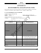
SIGNAL CHARACTERISTICS
Heading Valid Indicates that the heading source is providing valid heading information.
The status of the heading valid signal can be none, active high, or active
low and must be selected during system setup via the service menu.
CONNECTION Connector-Pin
Signal Name
P1-51 HEADING_FLG
CABLE See paragraph 2.6.4.
VOLTAGE None: Open or no connection
Active Low: (ref. to aircraft ground)
Valid: -5 V dc to +2.5 V dc
Invalid: +9 V dc to +32 V dc
Active High: (ref. to aircraft ground)
Valid: +9 V dc to +32 V dc
Invalid: -5 V dc to +2.5 V dc
INPUT IMPEDANCE >2 kΩ
INPUT CURRENT Active: Min: 1 mA
Max: 15 mA
Horizontal Sync Balanced horizontal sync from the WX-1000 Processor (if installed) and
output to the WX-1000/SKY497 display. Signal levels as specified in
RS-422.
CONNECTION Connector-Pin
Signal Name
P1-28 (HSYNC_IN+) From Processor
P1-29 (HSYNC_IN-) From Processor
P1-11 (HSYNC_OUT-) To Display
CABLE See paragraph 2.6.7.
VOLTAGE 0-5 V dc
CURRENT <100 mA
FREQUENCY 16.4 kHz
LOAD Z 1 kΩ
Lamp Outputs External annunciators are required when using an alternate display that
(above and below) is not capable of displaying above and below vertical modes. Outputs are
switched to ground when active. The lamps require a separate dc source
(constant or dimming circuit). If lamp voltage is an ac source then an
isolation relay must be used.
Depending on the vertical display mode selected the appropriate
annunciator will light. If in normal vertical display mode neither lamp will
light, if in above mode the ABV lamp will light, if in below mode then the
BLW lamp will light, and when unrestricted vertical mode is selected both
lamps will light.
CONNECTION Connector-Pin
Signal Name
P1-66 LP1OUT - (ABV)
P1-85 LP2OUT - (BLW)
CABLE Minimum 22 AWG wire for lengths up to 30 ft.
VOLTAGE ON: 0 V dc or Ground
OFF: Maximum +32 V dc or open
CURRENT Maximum current 300 mA.