
Install Manual

Preliminary
SKY899
Installation Manual
A-4
Rev. A
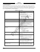
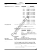
SIGNAL CHARACTERISTICS
CONNECTION Connector-Pin
Signal Name
P1-34 (GPWS)
CABLE Minimum 22 AWG wire for lengths up to 30 ft.
VOLTAGE WARNING: 0 V dc to +2.5 V dc (Aircraft Ground).
NO WARNING: +9 V dc to +30 V dc or open.
CURRENT <5 mA sourced.
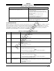
Debug Port
NO CONNECTION TO EXISTING AIRCRAFT WIRING. The Debug Port (RS-232) is
used for laptop interface to support system setup, post installation
checkout and troubleshooting. The port defaults to the following settings:
Baud Rate 19,200
Parity: None
Data Bits 8
Stop Bits 1
No handshaking
CONNECTION Connector-Pin
Signal Name
J7-2 DIAG_RX
J7-3 DIAG_TX
J7-5 DIAG_GND
J7-7 CTS
J7-8 RTS
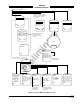
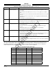
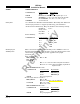
Heading Input These connections from the aircraft heading source (ARINC 407 & 407-1
(XYZ Synchro) Synchro System Manual) allow the unit to rotate the displayed data as the
aircraft turns. See Heading Flag in this appendix for flag input
specifications.
X(S1), Y(S3), Z(S2)
FREQUENCY Min: 50 Hz
Max: 1500 Hz
VOLTAGE
Min: 5.0 V ac rms (w/reduced angular resolution.)
Max: 14.0 V ac rms (external padding required for
higher levels.)
INPUT IMPEDANCE >50 kΩ
CONNECTION Connector-Pin
Signal Name
P1-46 HEADING_X
P1-47 HEADING_Y
P1-48 HEADING_Z
CABLE See paragraph 2.6.4.
H and C (high and low reference)
FREQUENCY Min: 50 Hz
Max: 1500 Hz
Spec says 400 Hz ±20%
VOLTAGE Min: 3 V ac rms
Max: 35 V ac rms
INPUT IMPEDANCE >50 kΩ
CONNECTION Connector-Pin
Signal Name
P1-49 HEADING_H
P1-50 HEADING_C
CABLE See paragraph 2.6.4.