
User's Manual


Chapter 1 – System Description
SKY899 Pilot’s Guide
1-4
Preliminary
Interaction of Major Components
Interaction of Major Components
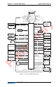
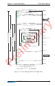
Figure 1-4 shows how the major components of the SKY899
connect to each other and to other aircraft systems.
Notes on Figure 1-4:
1. The optional radio altitude input affects the
SKY899 audio
inhibit feature, the ground intruder filtering feature, and
the sensitivity levels feature. (See chapter
4 for details.)
2. GPS nav data is only required if you plan on using
SKY899’s ADS-B feature (for intruder location enhance-
ment).
3. The
SKY899 works without a heading input, but experi-
ences degraded performance during high-rate-of-turn
maneuvers.
4. Having a weight-on-wheels input allows the
SKY899 to
automatically switch out of standby when you take off,
and into standby when you land.
5. The
SKY899 may be installed on aircraft with fixed landing
gear. The optional landing gear position input affects the
sensitivity levels feature. (See chapter
4 for details.)
6. The RGC250/radar indicator or alternate display can be in
place of, or in addition to the
WX-1000/SKY497 display for
TAS installations, but one of the two must be used for
TCAS I installations.
7. Only required when using an alternate display that doesn’t
display vertical display mode indications.
Functional Description
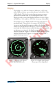
The SKY899 is an active system that operates as an aircraft-to-
aircraft interrogation device. The
SKY899 interrogates aircraft
transponders in the surrounding airspace (within a
35 nmi
horizontal radius) similar to the way ground-based radar
interrogates aircraft transponders. When the
SKY899 receives
replies to its interrogations, it computes the responding
aircraft’s range, relative bearing, relative altitude, and closure
rate. The
SKY899 also receives any ADS-B broadcasts from the
responding aircraft and uses that information along with your
own aircraft
Global Positioning System (GPS) navigation (nav)
data to enhance the computed relative position of the respond-