
User Guide Part 2
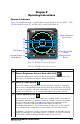
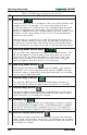
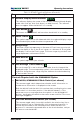
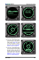
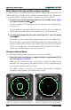
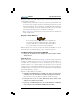
Table Of Contents
- Chapter 2 Operating Instructions
- Controls & Indicators
- Turn On the SKY497
- Run the Operator-Initiated Self Test
- Switch Between Standby and Normal Operating Mode
- Change the Display Range
- Change the Altitude Display Mode
- Switch Between SKYWATCH and STORMSCOPE Modes (Optional)
- Observe the Display
- Respond to Traffic Advisories
- Turn Off the SKY497 and the Optional WX-1000
- Failure Response
- Operate the Optional WX-1000 When the SKY497 is Removed
- Operate the SKY497 When the Optional WX-1000 is Removed
- Chapter 3 Principles of Operation
- Chapter 4 Display Interpretation
- Chapter 5 Specifications
- Chapter 6 Warranty Information
- Record of Important Information
- Back Cover

Pilot’s Guide 2-3
SKY497
Operating Instructions
Table 2-1. SKY497 Controls and Indicators (Continued)
AB
V
No Description
11 Altitude Display Mode Indicator
This indicator displays the name of the currently selected altitude display
mode:
ABV
(look up),
BLW
(look down), or
NRM
(normal). This indicator
does not appear when the
SKY497
is in standby.
12 Test Button
This button starts a
SKY497
self test when the
SKY497
is in standby.
13 Other Traffic
This symbol represents traffic detected within the selected display range
and altitude display mode that does not generate a TA.
14 Range Rings
The outer range ring represents a distance of 6 nmi from your aircraft
when the display is set on the 6 nmi range, or a distance of 2 nmi when
the display is set on the 2 nmi range. The inner range ring on the 6 nmi
range represents a distance of 2 nmi.
15 Own Aircraft
This symbol represents your aircraft.
16 Out-of-Range Traffic Advisory
An out-of-range TA is one in which the intruder aircraft is beyond the
displayed range. The corresponding symbol is this semicircle located at
a position along the outer range ring that indicates the relative bearing
of the intruder aircraft.
Controls Required with the
STORMSCOPE
Option:
–
SKYWATCH/STORMSCOPE
Mode Switch (not shown)
This remote toggle switch determines whether traffic information or
thunderstorm information is displayed on the screen.
Both the
SKY497
and the
WX-1000
continue their tracking functions even
if the switch is in the other position. If the
SKY497
detects a TA or
generates an error message when the switch is in the
STORMSCOPE
position, the display will switch to the traffic screen until the TA or error
message disappears.
–
WX-1000
Maintenance Switch (not shown)
This remote toggle switch (normally installed in the avionics bay) has a
Normal position and an Override (
WX-1000
maintenance) position. It
should only be moved to the Override position when the
WX-1000
processor is removed or powered down at the circuit breaker, and you
still want to use the
SKY497
.