
User Guide Part 1

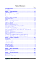

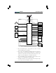
Table Of Contents

SKY497
System Description
Pilot’s Guide 1-3
5. This audio inhibit input is only required if you have a Ground
Proximity Warning System installed.
6. The position of the
SKYWATCH/STORMSCOPE
mode switch deter-
mines whether the display displays
SKYWATCH
or
STORMSCOPE
information. The switch also determines whether the buttons on the
display control the
SKYWATCH
or
STORMSCOPE
system.
7. The optional
MFD
or
RGC250
/radar indicator can be in place of, or in
addition to the standard
WX-1000/SKY497
display.
8. The flight data
RS-422
output and the diagnostic
RS-232
input/output
are not required for normal
SKY497
operation.
Aircraft
Audio
System
Aircraft Power
Flight Data (RS-422)
8
SKYWATCH
Display
ARINC429
SKYWATCH
Control
Diagnostic Commands
and Status (RS-232)
8
Arinc 429 Radio
Altimeter or Flight
Data Computer
(Optional)
SKYWATCH/
STORMSCOPE
Mode Switch
Data
Recorder
(Optional)
Third-Party
MFD or BFG
RGC250/
Radar
Indicator
(Optional)
7
Diagnostic
Equipment
(Optional)
Squat Switch
(Optional)
GPWS (Optional)
Landing Gear
Switch (Optional)
WX-1000
Processor
STORMSCOPE
WX-1000
Maintenance
Switch
Aircraft Compass
System
Aircraft
Suppression Bus
Encoding Altimeter
Arinc 429
Radio Altitude
1
SKYWATCH/
STORMSCOPE
Mode Selection
Barometric Altitude
2
SKYWATCH
STORMSCOPE
or
Display
6
STORMSCOPE
Display
TRC On/Off Control
When WX-1000 is
Powered Down or
Removed
WX-1000
On/Off Control
Display Power/
TRC On/Off Control
Display Power
TRC
SKYWATCH
STORMSCOPE
or
Control
6
STORMSCOPE
Control
On/Off Control
STORMSCOPE
Option
14 or 28 V dc
Aural TA's
Heading
TX/RX Inhibit
Landing Gear Position
4
Audio Inhibit
5
Weight On Wheels
Display
Directional
Antenna
Transponder
Replies
Transponder
Replies
Transponder
Interrogations
SKY497
Intruder Aircraft
Transponder
Interrogations
2,3
Figure 1-4. SKY497 Simplified Functional Diagram