
User Guide Part 1
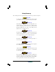
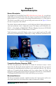
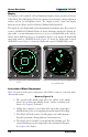
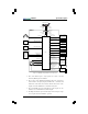
Table Of Contents

1-2 Pilot’s Guide
System Description
SKY497
Display
The display is a self-contained,
3-ATI
-sized unit with a high resolution, green monochrome
Cathode Ray Tube (
CRT
) display. The bezel contains four momentary contact push-button
switches and an on/off/brightness knob. The display provides control and display
functions for the
SKY497
and for a
WX-1000
STORMSCOPE
(if installed).
The display does not display traffic and storm information simultaneously. The position of
a remote
SKYWATCH/STORMSCOPE
mode switch determines whether the display dis-
plays traffic or storm information; however, if you’re in
STORMSCOPE
mode and the
SKY497
detects traffic that may pose an immediate threat to your aircraft, the display will
temporarily switch to
SKYWATCH
mode. Figure 1-2 shows the display with a typical
SKYWATCH
screen. Figure 1-3 shows the display with a typical
STORMSCOPE
screen.
MENU
CLEAR
120$
25
100nm
300$
BRT
OFF
NRM
6
nm
-13
+01
+25
+10
+05
BRT
OFF
Figure 1-3.Display with Typical STORMSCOPE
Screen (Optional)
Figure 1-2.Display with Typical
SKYWATCH
Screen
Interaction of Major Components
Figure 1-4 shows how the major components of the
SKY497
connect to each other and to
other aircraft systems.
Notes on Figure 1-4:
1.The optional radio altitude input affects the
SKY497
audio inhibit
feature, the ground target filtering feature, and the sensitivity levels
feature. (See chapter 3 for details.)
2.A flight data computer or other Arinc 429 output device may replace
individual analog sensors for supplying barometric altitude & heading.
3.The
SKY497
will work without a heading input, but it will experience
degraded performance during high-rate-of-turn maneuvers.
4.The
SKY497
may be installed on aircraft with fixed landing gear. The
optional landing gear position input affects the sensitivity levels feature.
(See chapter 3 for details.)