
Install Manual Part 3
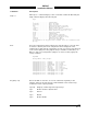
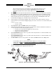
Table Of Contents
- CHAPTER 4- MAINTENANCE
- APPENDIX A - SIGNAL & CABLE CHARACTERISTICS
- APPENDIX B - CHECKOUT USING TCAS-201 RAMP TEST SET
- APPENDIX C - CHECKOUT USING T-49C FLIGHTLINE TESTER
- APPENDIX D - USING THE TERMINAL DEVICE
- APPENDIX E - CHECKOUT USING ALTERNATE DISPLAY

SKY497
Installation Manual
E-2
Rev. C
NOTE
After power up, it may take a couple of minutes for the altitude encoder to
return a valid altitude to the transponder and SKY497.
3. Turn SKY497 ON. After approximately thirty seconds the display will show the standby screen.
NOTE
If the TRC has not been calibrated to the directional antenna, the display may show
a FAIL message. Calibrate the system (see step 4 below).
4. At the terminal device, type Cal <Enter>. Verify the Re-Calibration Successful! is displayed.
5. Type Config <Enter>. Verify status of the configuration jumpers displayed on the screen. (You may
need to page up in order to see all of the data. See Appendix D for example.) Once correct
configuration is verified type Save <Enter>.
Change the status of the landing gear, squat switch, and altitude sensors. Type Config <Enter> again
and verify that the displayed information changed correctly (i.e., sensing of these signals).
6. At the terminal device, type the commands listed below. For each command verify the sensor
information displayed is correct (see Appendix D for examples). If the information is not correct, the
configuration setting may be wrong or the sensor communication with the TRC may have failed.
Check operation of the sensor and cables between the TRC and sensor.
Arinc429 <Enter>
Arinc735 <Enter>
Bar <Enter>
Rad <Enter>
Head <Enter> (Change heading of aircraft and verify heading changes.)
7. At the alternate display, perform the SKYWATCH self-test (see paragraph E.3.1).
8. At the terminal device, type Ground Test <Enter>.
9. At the alternate display, change the display ranges (if applicable) and verify display patterns are
correct.
10. Select the 6 nautical mile range.
11. Change the altitude display modes from normal (NRM), below (BLW), and above (ABV). Verify that
the system toggles through the altitude display modes correctly.
12. Select the normal (NRM) mode.
13. Position the aircraft with the nose aligned on any 90 degree heading. Avoid areas within 250 ft of
obstructions (e.g., hangers, large aircraft, control towers, etc.) where there is a potential for multipath
problems. Locate and mark test points at 30 degree intervals (i.e., 000, 030, 060, 090, 120, 150, 180,
210, 240, 270, 300, and 330 degrees) with respect to the directional antenna. Mark these points at the
same distance, between 100 and 150 ft, from the aircraft.
14. Position the TT391 Flightline Tester on one of the test points identified above.
CAUTION
The Flightline Tester is not weatherproof when the lid is open. Do not setup
or operate the Flightline Tester in conditions of rain, sleet, etc.
15. Setup and verify operation of the TT391 Flightline Tester:
a. Open the chassis lid and remove the lid from the chassis by sliding the lid off of the hinge pins
(sliding it to the right). The lid "stay" must be removed from the lid before mounting. The stay
will pop off of the lid. (The stay is the hinged part that props the lid open on the chassis).