
Install Manual Part 3
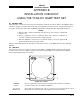
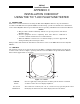
Table Of Contents
- CHAPTER 4- MAINTENANCE
- APPENDIX A - SIGNAL & CABLE CHARACTERISTICS
- APPENDIX B - CHECKOUT USING TCAS-201 RAMP TEST SET
- APPENDIX C - CHECKOUT USING T-49C FLIGHTLINE TESTER
- APPENDIX D - USING THE TERMINAL DEVICE
- APPENDIX E - CHECKOUT USING ALTERNATE DISPLAY

SKY497
Installation Manual
C-4
Rev. C
13a. Change the aircraft's transponder from STBY mode to the ON position.
14. Position the T-49C Flightline Tester on one of the test points identified in previous step.
CAUTION
The Flightline Tester is not weatherproof when the lid is open. Do not setup
or operate the Flightline Tester in conditions of rain, sleet, etc.
15. Setup and verify operation of the T-49C Flightline Tester with the HI/LOW power switch in the HI
position and then:
a. Set the TCAS INTRUDER selector switch of the T-49C to the ATCRBS/Mode-S XPDR TEST
position and press TEST and the INTERROGATE. This will store the aircraft’s barometric
altitude in the T-49C.
NOTE
The T49-C will display the pressure altitude of the aircraft under test.
b. Verify that the SKY497 display shows the standby screen (figure C-3) and then press soft-key
(4), labeled OPR. Select NRM mode and 6 nm range by pressing appropriate soft-key's.
c. Set the TCAS INTRUDER selector switch to the ATCRBS position and the SCENARIO selector
switch to the 0 altitude offset position. Press INTERROGATE, and when the range on the
display decreases to 5 NM, press TEST. This will freeze the scenario and represent a stationary
intruder aircraft 5 NM away at the same altitude as the UUT aircraft. Verify that the SKY497
displays, in the direction (±30 degrees) of the T-49C, a symbol for other traffic (i.e., open
diamond) at 5 NM. Target will be displayed in level flight at own aircraft altitude (i.e., “00”
displayed above the traffic symbol).
NOTES
1) If the display reflects a gross error in target bearing, check the SKY497
directional antenna cables at TRC connectors J9 (sum port) and J11
(difference port). They may be reversed. A further indication of this
condition would be a target that moved in a counter-clockwise direction
when the T-49C is moved in a clockwise direction.
2) Multiple targets or a faulty bearing may result from multipath distortion
(see step 1).
3) During these tests, the SKY497 may detect and display other active
targets.
4) To obtain a better line of sight, it may be necessary to elevate the
antenna.
d. Move the T-49C to each test point and verify that the display shows the corresponding bearing
displacement.
NOTE
It is necessary to wait a few seconds after moving to let the test target stabilize
in position.
16. This completes testing with the T-49C, reattach top lid of the T-49C.
17. If installed, TURN ON the radio altimeter.
18. This completes the post installation checkout procedure.