
Install Manual Part 3
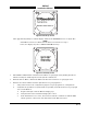

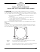
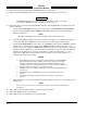
Table Of Contents
- CHAPTER 4- MAINTENANCE
- APPENDIX A - SIGNAL & CABLE CHARACTERISTICS
- APPENDIX B - CHECKOUT USING TCAS-201 RAMP TEST SET
- APPENDIX C - CHECKOUT USING T-49C FLIGHTLINE TESTER
- APPENDIX D - USING THE TERMINAL DEVICE
- APPENDIX E - CHECKOUT USING ALTERNATE DISPLAY

SKY497
Installation Manual
C-3
Rev. C
Figure C-3. Standby Screen
3. Turn SKY497 OFF and then enter the Service Menu (see paragraph 4.4) by holding the left two
buttons (soft-keys 1 and 2) depressed as the system is turned ON.
4. From the Service Menu, calibrate the TRC to the directional antenna (see paragraph 4.4.1).
5. Return to the Service Menu and select System Data (see paragraph 4.4.3).
a. Verify status and save the configuration jumpers (see paragraph 4.4.3.2, Configuration).
b. Verify that the system has recognized and is responding to installed sensors (see paragraph
4.4.3.3, Data Monitor).
1) Sequence through each Data Monitor display page.
2) Verify that the sensor information displayed is correct.
3) If the information is not correct, the sensor has failed to communicate with the TRC.
Check operation of the sensor and cables between the TRC and sensor.
4) Change the status of the landing gear, squat switch, altitude, and heading sensors. Verify
that the display shows the correct input (i.e., sensing of these signals).
6. Exit the Service Menu. Verify that the display shows the standby screen (figure C-3) and then press
Soft-key (4), labeled OPR.
7. Verify operation of range function. Soft-key (3) is labeled to indicate the current range. Press Soft-key
(3) to toggle the display range between 2 and 6 nm.
8. Select the 6 nautical mile range.
9. Verify that the system toggles through the altitude display modes. Soft-key (2) is labeled to indicate
the current mode. Press Soft-key (2) to select normal (NRM), below (BLW), and above (ABV).
10. Select the NRM (normal) mode.
11. If installed, turn the radio altimeter OFF.
12. Do the
SKYWATCH self-test (see para 3.4).
13. Position the aircraft with the nose aligned on any 90 degree heading. Avoid areas within 250 ft of
obstructions (e.g., hangers, large aircraft, control towers, etc.) where there is a potential for multipath
problems. Locate and mark test points at 30 degree intervals (i.e., 000, 030, 060, 090, 120, 150, 180,
210, 240, 270, 300, and 330 degrees) with respect to the SKY497 directional antenna. Mark these
points at the same distance, between 100 and 150 ft, from the aircraft.