
Install Manual Part 3
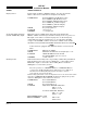
Table Of Contents
- CHAPTER 4- MAINTENANCE
- APPENDIX A - SIGNAL & CABLE CHARACTERISTICS
- APPENDIX B - CHECKOUT USING TCAS-201 RAMP TEST SET
- APPENDIX C - CHECKOUT USING T-49C FLIGHTLINE TESTER
- APPENDIX D - USING THE TERMINAL DEVICE
- APPENDIX E - CHECKOUT USING ALTERNATE DISPLAY

SKY497
Installation Manual
A-8
Rev. C
SIGNAL CHARACTERISTICS
Suppression Bus I/O The SKY497 outputs a 100 µs (± 5 µs) suppression pulse on the aircraft
suppression bus (see para 2.6.8). In addition, the SKY497 receives
suppression signals from all other devices on the suppression bus (e.g.,
transponder, DME). (Reference ARINC 735-2 and DO-197A.)
CAUTION
The aircraft transponder must have suppression circuitry to ensure
that
SKYWATCH does not paint itself as a target (e.g., TA).
CONNECTION TRC P1-89 (SUP_BUS)
CABLE Any size low capacitance shielded cable may be
used.
VOLTAGE 18 - 70 V dc input, greater than 20 V dc output.
CURRENT 0.3 A output max.
FREQUENCY 100 µs positive pulse output, DC-1 mHz input.
SOURCE Z 2 kΩ
LOAD Z 10.5 kΩ
MAX CAPACITANCE <50 pF
Vertical Sync Balanced vertical sync from the WX-1000 Processor (if installed) and
output to the display. Signal levels as specified in RS-422.
CONNECTION TRC P1-61 (VSYNC_IN_HI) From Processor
TRC P1-60 (VSYNC_IN_LO) From Processor
TRC P1-63 (VSYNC_OUT_HI) To Display
TRC P1-62 (VSYNC_OUT_LO) To Display
CABLE See paragraph 2.6.3.
VOLTAGE 0-5 V dc
FREQUENCY 60 Hz
SOURCE Z 1 kΩ
Video Output Balanced video from the WX-1000 Processor (if installed) and output to
the display. Signal levels as specified in RS-422.
CONNECTION TRC P1-36 (VIDEO_IN_HI) From Processor
TRC P1-35 (VIDEO_IN_LO) From Processor
TRC P1-38 (VIDEO_OUT_HI) To Display
TRC P1-37 (VIDEO_OUT_LO) To Display
CABLE See paragraph 2.6.3.
VOLTAGE 0-5 V
CURRENT <100 mA
FREQUENCY <15 mHz
LOAD Z 1 kΩ