
Install Manual Part 3
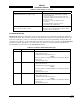
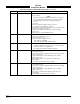
Table Of Contents
- CHAPTER 4- MAINTENANCE
- APPENDIX A - SIGNAL & CABLE CHARACTERISTICS
- APPENDIX B - CHECKOUT USING TCAS-201 RAMP TEST SET
- APPENDIX C - CHECKOUT USING T-49C FLIGHTLINE TESTER
- APPENDIX D - USING THE TERMINAL DEVICE
- APPENDIX E - CHECKOUT USING ALTERNATE DISPLAY

SKY497
Installation Manual
4-16
Rev. C
Table 4-2. Installation Related Error Messages (Continued)
ERROR NO. MESSAGE Remarks
ERROR 020 Barometric Altitude Input a. Check altimeter source. Is the unit turned on and been given enough
time to warm up.
NOTE
When interfacing via an ARINC 429 serial data bus, at power-up
the TRC must adjust (auto-baud) to the speed of the incoming
data. Normally the TRC will lock-on after approximately 15
seconds.
b. Cycle power.
c. Ensure that barometric altitude is input from only one
source (Gray Code or ARINC 429, not both).
d. Encoded inputs can be checked from the system configuration screen
(para 4.4.3.2, Configuration - Page 2).
e. Using the Data Monitor, verify barometric source and altitude
(para 4.4.3.3).
f. Check wiring associated with altimeter source.
ERROR 021 Power Supply a. Using the Data Monitor, observe internal voltage measurements
(para 4.4.3.3, Data Monitor - Page 5).
b. Check aircraft power source.
c. Check power input at mating connector.
P8-A +28V (10.5-34V PWR)
P8-B +28V_RET (AIRCRAFT PWR RETURN)
ERROR 30 Check Configuration Configuration jumpers not saved or changed and need validated.
a. Using the Configuration menu, verify pages 1, 3 and 4 are correct
then save (para 4.4.3.2, Configuration).
b. Check wiring associated with configuration jumpers.
ERROR 152 HDG Invalid synchro XYZ input.
a. Check heading source.
b. Verify status of heading configuration jumpers (input source and flag
sense - para 4.4.3.2).
c. Using the Data Monitor, verify heading data (source, heading
& flag - para 4.4.3.3).
d. If the heading signals become valid, the system will recover
automatically.
e. Check wiring associated with compass heading.
ERROR 153 HDG Invalid heading reference (400 Hz).
a. Check heading source.
b. Verify status of heading configuration jumpers (input source and flag
sense - para 4.4.3.2).
c. Using the Data Monitor, verify heading data (source, heading
& flag - para 4.4.3.3).
d. If the reference signal becomes valid, the system will recover
automatically.
e. Check wiring associated with compass heading.