
Install Manual Part 3
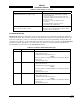
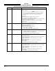
Table Of Contents
- CHAPTER 4- MAINTENANCE
- APPENDIX A - SIGNAL & CABLE CHARACTERISTICS
- APPENDIX B - CHECKOUT USING TCAS-201 RAMP TEST SET
- APPENDIX C - CHECKOUT USING T-49C FLIGHTLINE TESTER
- APPENDIX D - USING THE TERMINAL DEVICE
- APPENDIX E - CHECKOUT USING ALTERNATE DISPLAY

SKY497
Installation Manual
4-15
Rev. C
Table 4-1. Fault Isolation (Continued)
SYMPTOM CORRECTIVE ACTION
SKYWATCH paints itself as a target (e.g., TA). a. Verify suppression bus shielded cable is grounded
correctly at both ends.
b. Connect an oscilloscope to the suppression bus and
verify that the SKY497 suppression pulse (100 µs ±5 µs)
exceeds +15 V dc.
c. If less than +15 V dc, the suppression bus is
overloaded.
d. Check all equipment connected to the bus.
e. Repair/replace the offending device.
SKYWATCH TRC497 has been removed for service; the
WX-1000
Stormscope
fails to operate.
Check the adapter plug (see para 4.7). If the TRC497 is
removed for service, an adapter plug is required to permit
continued operation of the WX-1000.
4.6 ERROR MESSAGES
SKYWATCH firmware is designed to generate error messages associated with a particular condition or
step in the program. The 20 most recent errors detected by the system are saved in the System Log (see
para 4.4.2). System Log can be accessed with a terminal device by using the Dump command. For your
convenience, in table 4-2, we have listed the error messages that have been associated with SKYWATCH
installations. Where appropriate, procedures that may assist in resolving installation problems are
provided. When a severe error occurs SKYWATCH will fail.
Table 4-2. Installation Related Error Messages
ERROR NO. MESSAGE Remarks
ERROR 016 RF BITE a. Check directional antenna and associated cables.
b. Turn system power ON.
c. Calibrate directional antenna (para 4.4.1).
NOTE
Ensure transponder is in standby and DME is OFF while doing calibration.
d. Cycle power.
e. Run pilot initiated self-test.
ERROR 017 RF Amplitude a. Check directional antenna and associated cables.
b. Turn system power ON.
c. Calibrate directional antenna (para 4.4.1).
NOTE
Ensure transponder is in standby and DME is OFF while doing calibration.
d. Cycle power.
e. Run pilot initiated self-test.
ERROR 18 RF Angle a. Check directional antenna and associated cables.
b. Turn system power ON.
c. Calibrate directional antenna (para 4.4.1).
NOTE
Ensure transponder is in standby and DME is OFF while doing calibration.
d. Cycle power.
e. Run pilot initiated self-test.