
Install Manual Part 3
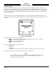
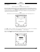
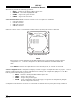
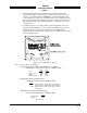
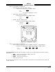
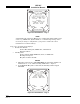
Table Of Contents
- CHAPTER 4- MAINTENANCE
- APPENDIX A - SIGNAL & CABLE CHARACTERISTICS
- APPENDIX B - CHECKOUT USING TCAS-201 RAMP TEST SET
- APPENDIX C - CHECKOUT USING T-49C FLIGHTLINE TESTER
- APPENDIX D - USING THE TERMINAL DEVICE
- APPENDIX E - CHECKOUT USING ALTERNATE DISPLAY

SKY497
Installation Manual
4-10
Rev. C
Figure 4-12. Data Monitor - Page 1
NOTE
Values displayed on the Data Monitor are continuously updated. The sensor
source (e.g., ARINC 429, Synchro XYZ, etc.) is latched at power-up. If it is
necessary to change a configuration, cycle power to ensure the correct
information is read into memory.
Page 1 of 5 (see figure 4-12) displays:
• Barometric Altitude
Source (Encoded Inputs, ARINC 429, or Simulated)
Altitude (in Feet)
• Heading Data
Source (Synchro XYZ, ARINC 429, None, or Simulated)
Heading (in Degrees)
Flag Line (Valid or Invalid)
NOTES
1. When the system is set to GROUND TEST, the barometric altimeter is
simulated to 50,000 ft and the heading simulated to 0 degrees.
2. If an INVALID “Flag Line” is detected, the “Heading” will be flagged
INVALID.
Figure 4-13. Data Monitor - Page 2