
Install Manual Part 2
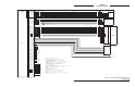
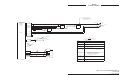
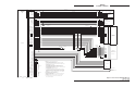
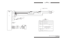
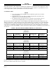
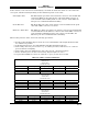
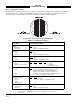
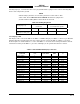
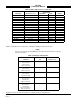
Table Of Contents

SKY497
Installation Manual
2-15
Rev. C
Heading flag logic, as detailed in table 2-4, is programmed with a jumper between P1-68 (Heading Flag
Sense) and configuration ground.
NOTE
If the heading system has a low level flag between 1.5 VDC and 2.7 VDC
(when valid), P1-68 (HEADING FLAG SENSE) should not be jumpered to
ground and P1-53 (HDG_FLG+) must remain unconnected.
Table 2-4. Heading Flag Action
Heading Flag Logic
FLAG SENSE LOW
(P1-68 Open)
FLAG SENSE HIGH
(P1-68 Jumpered to ground.)
Heading Status VALID FLAGGED VALID FLAGGED
P1-53 Relative to P1-52
(HDG_FLG+ - HDG_FLG-)
<1 V >5 V >5V <1V
2.6.3 Display Cable
The display cable connects the TRC to the WX-1000/SKY497 Display. If a WX-1000 Stormscope® Weather
Mapping System is installed, the same type cable is used to connect the TRC to a WX-1000 processor.
Refer to figure 2-2 (without WX-1000) or 2-3 (with WX-1000) for interconnect wiring information. Pinout
information relating to the WX-1000 processor and display is also provided in tables 2-5 and 2-6.
Table 2-5. WX-1000/SKY497 Display Connection
Display WIRE COLOR TRC
FUNCTION P101 SUB-CABLE WIRE P1
(Inner Jackets) 2
DPWR+15_OUT 19 WHITE WHITE P1-7
DPWR-15_OUT 14 WHITE ORANGE P1-6
DSPLY_GND 18 WHITE BLUE P1-14
HSYNC_OUT_HI 6 BLUE BLUE P1-49
HSYNC_OUT_LO 5 BLUE WHITE P1-48
VSYNC_OUT_HI 9 ORANGE WHITE P1-63
VSYNC_OUT_LO 10 ORANGE BLUE P1-62
VIDEO_OUT_HI 8 RED WHITE P1-38
VIDEOOUT_LO 7 RED BLUE P1-37
PWR_SW_HI 22 (SW2*) GREEN WHITE P1-11
PWR_SW-LO 23 (SW2*) GREEN BLUE P1-3
SFTKEY1_IN 13 BLACK WHITE P1-85
SFTKEY2_IN 12 BLACK BLUE P1-84
SFTKEY3_IN 25 YELLOW WHITE P1-83
SFTKEY4_IN 24 YELLOW BLUE P1-82
*SW2 required if WX-1000 Processor installed (see figure 2-2).