
Install Manual Part 2
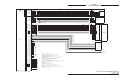
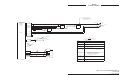
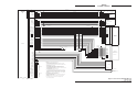
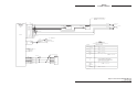
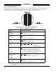
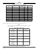
Table Of Contents

SKY497
Installation Manual
2-11
Rev. C
2.5 DISPLAY LOCATION
The display should be mounted in a location easily accessible and clearly visible to the pilot. In selecting a
location, consider the following:
Magnetic Effect Where possible to avoid it, the display should not be mounted within
3 inches (8 cm) of an electric turn and bank indicator, as the magnetic
effect of the turn and bank motor may affect the display presentation. (a
common symptom of magnetic interference is a wobbling or vibrating
display raster.)
NOTE
If it is necessary to mount the display unit next to a device that may affect
the CRT display, magnetic shielding material can be placed around the
display unit. Shielding material is available from BFG Avionics Systems.
Specify P/N 78-8060-5882-8 when ordering.
Panel Depth Adequate depth must be available behind the instrument panel to allow for
the display, the display connector, and excess display cable. Remember, a
service loop is necessary to allow access to the display connector when
removing the display or inserting it into the instrument panel.
Cooling While the display has no special cooling requirements, it should be
mounted to permit adequate ventilation.
Viewing Angle The viewing angle for the CRT display is not a critical factor. The most
favorable mounting position would be near eye level and no more than
arms length from the principle user of the instrument.
2.6 CABLE REQUIREMENTS AND FABRICATION
NOTE
All wiring must be in accordance with industry accepted methods,
techniques and practices.
The installer will supply and fabricate all system cables. Appendix A defines the electrical characteristics
of all input and output signals and identifies the cable requirements for each signal. Refer to figure 2-2
(without WX-1000) or 2-3 (with WX-1000) for interconnect wiring information. Required connectors and
contact pins are supplied in the installation kits.
The length and routing of the external cables must be carefully studied and planned before attempting
installation of the equipment. Observe the following precautions:
• Note the signal characteristics of flag lines and discrete signal inputs; an external relay may be
required to provide proper polarity or "sense" of the signals.
• All cable routing should be kept as short and direct as possible.
• Avoid sharp bends (do not exceed the minimum bend radius detailed in table 2-1).
• Avoid routing the cables too close to aircraft control cables.
• Avoid routing cable near the ADF, comm radio, or transponder antenna cables (allow at least a 12
inch separation).
• Avoid routing cable near power sources (e.g., 400 Hertz generators, trim motors, etc.) and near
power for fluorescent lighting.
• To limit the possibility of wire chafing, it is recommended that heat shrink sleeving be installed
over the wire bundle between the shield termination’s (inside the connector backshell) and the
connector cable clamp.
• Observe all wiring notes on interconnect wiring diagram.