
Install Manual Part 2
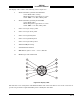
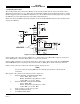
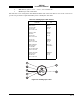
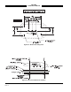
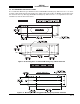
Table Of Contents

SKY497
Installation Manual
2-23
Rev. C
2.6.13 Landing Gear Switch Input
This signal line is to be connected to the landing gear switch to sense the position of the landing gear.
For the GEAR input (P1-87) line, use #22 AWG (minimum) unshielded cable. Routing and length are not
critical to system operation.
If the aircraft does not have a landing gear switch input (e.g., fixed-gear aircraft), leave this input
unconnected. With this configuration, if no ARINC 429 compatible radio altimeter is installed, the system
will default to the highest TA sensitivity level (level B) and audio TA announcements (i.e., “traffic, traffic”)
will not be inhibited during takeoff and landing.
2.6.14 Power Cable
The power cable (not supplied) runs from the aircraft circuit breaker panel to the TRC. The power cable is
connected to the TRC using the MS3126F12-3S connector included in the TRC installation kit. For the
power cable, use #16 AWG (minimum) twisted shielded pair cable (Beldon 83322, Alpha 2826/2, or
equivalent).
NOTE
For 14 V aircraft systems a 7.5 A circuit breaker is required and for 28 V
systems a 5 A circuit breaker is required. The circuit breaker may be selected
to match components of the individual aircraft.
The positive wire (P8-A) connects to the circuit breaker. The negative wire (P8-B) connects to the aircraft
power return. Terminate the shield to airframe ground at the power source. Power cable routing and
length are not critical to system operation.
2.7 ANTENNA INSTALLATION
The following paragraphs provide installation details for directional antenna. The installer must ensure
the immediate antenna installation area is clean and prepared so that the antenna is electrically bonded
(metal-to-metal contact) to the aircraft. To provide optimum bonding through the mounting holes, prepare
the surfaces with Alodine No. 1001.
To facilitate mounting to the airframe, the dimensions shown in figure 2-8 can be used to locate and drill
mounting and connector access holes. Connection to the antenna should be made in accordance with the
system interconnect diagram (figure 2-2 or 2-3).
NOTE
A doubler plate (not supplied) is required to reinforce the aircraft skin.
1. Connect each of the three antenna cables. Check to ensure that each cable is connected to the correct
antenna connector. Each connector/cable has a matching color band (see note para 2.6.1).
2. Attach the antenna to the aircraft, with the special adapter plate and o-ring, using 10-32 hardware
provided. See figure 2-9.
NOTES
1. When mounting the antenna remove the O-ring from the bag and install it
in the O-ring groove on the bottom of the antenna.
2. The antenna must be sealed to the airframe. For pressurized aircraft, use
a sealant that meets the requirements of SAE AMS-S-8802 such as
Flamemaster® CS3204 class B. For non-pressurized aircraft, use a non-
corrosive sealant that meets the physical requirements of MIL-A-46146
such as General Electric RTV162.