
Install Manual Part 2
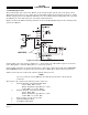
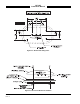
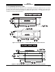
Table Of Contents

SKY497
Installation Manual
2-21
Rev. C
2.6.6 Altimeter Input Cable
NOTE
Only one altimeter input source (Gray Code or ARINC 429, not both) should be
connected. The altimeter input should be from the same source that is interfaced with
the transponder or it must be at least as accurate as that source, i.e., ± 125 ft.
These signals are Gilham Code inputs coming from an airdata computer or altitude digitizer. These 10
lines may be connected in parallel with the aircraft transponder. If the aircraft is equipped with selectable
altitude encoders, connect the altitude inputs so that SKY497 is always connected to the selected encoder.
(Reference ARINC 572-1.)
Altitude encoder connection:
A1 -to- P1-40 B1 -to- P1-51 C1 -to- P1-58 D4 -to- P1-72
A2 -to- P1-41 B2 -to- P1-56 C2 -to- P1-59
A4 -to- P1-50 B4 -to- P1-57 C4 -to- P1-71
ALTITUDE COMMON - to P1-81
NOTE
If the aircraft has switched encoders that uses 28V RETURN or AIRCRAFT GROUND
as reference for encoder selection, then ALTITUDE COMMON should be left
unconnected.
For each connection use #22 AWG (minimum). Cable runs should be as short as practicable. Refer to figure
2-2 or 2-3 for detailed interconnect wiring information.
2.6.7 Audio Alert Output Cable
Audio output from the TRC is directly compatible with industry standard aircraft audio panels. There is no
internal audio adjustment. Audio levels are adjusted at the aircraft audio panel. This output is disabled
when a GPWS alarm is detected and remains disabled until the warning clears.
Use #22 AWG (minimum) twisted shielded pair cable for lengths up to 30 ft. . Cable runs should be as
short as practicable.
• Connect 600-ohm audio systems to P1-92 (AUDIO_H).
• Connect 150-ohm audio systems to P1-91 (AUIDO_L).
• Audio common is connected to P1-90 (AUDIO_C)
Refer to figure 2-2 or 2-3 for detailed interconnect wiring information.
2.6.8 Suppression Bus I/O
The TRC497 outputs (P1-89) a 100 µs (± 5 µs) suppression pulse on the aircraft suppression bus. In
addition, the TRC497 receives suppression signals from all other devices on the suppression bus (e.g.,
transponder, DME). (Reference ARINC 735-2 and DO-197.)
CAUTION
The aircraft transponder must have suppression circuitry to ensure that
SKYWATCH does not paint itself as a target (e.g., TA).
Any size low capacitance shielded cable may be used. Cable runs should be as short as practicable and the
shields should be grounded at both ends of the cable. Refer to figure 2-2 or 2-3 for detailed interconnect
wiring information.