
Install Manual Part 1
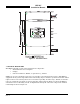
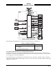
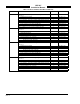
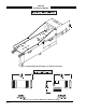
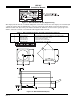
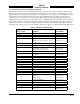
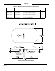
Table Of Contents

SKY497
Installation Manual
1-8
Rev. C
Figure 1-7. WX-1000/SKY497 Display Equipment Tag
The display unit mounts in a standard 3ATI panel cutout. All connections to the display are made through
a single 25-position male D-subminiature connector on the back panel. Figure 1-8 depicts the indicator
dimensions. The last digit of the part number identifies the different versions (refer to paragraph 1.4.1).
Table 1-3 lists the contents of an installation kit supplied with each unit.
Table 1-3. WX-1000/SKY497 Display Installation Kit P/N 817-10802-001
QUANTITY PART NUMBER DESCRIPTION
4 26-1001-6374-5 Screw, Machine, 6-32 x 3/4 in. Phillips Pan Head, Black Oxide
1 M24308/2-283F Connector, 25 Position Recpt. Shell
1 26-1006-2426-6 Connector Backshell, DB25
2 26-1006-1089-3 Connector Lock Post Assembly
25 M39029/63-368 Connector Socket, Screw Machine
Figure 1-8. WX-1000/SKY497 Display