USER MANUAL Copyright ©2022 Flysky Technology co., ltd This product is only for 15 years old or above.
Thank you for purchasing our product, an ideal radio system for beginners or experienced users. In order to ensure your safety, and the safety of others, read this manual carefully before using this product. If you encounter any problem during use, refer to this manual first. If the prob lems persists, contact your local dealer or visit our service and support website: www.flysky-cn.
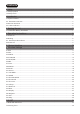
Contents 1. Safety .............................................................................................................................................1 1.1 Safety Symbols ...................................................................................................................................................................... 1 1.2 Safety Guide..................................................................................................................................................
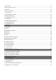
7.3 Gyro Gain..................................................................................................................................................................................30 7.4 RX Interface Protocol...........................................................................................................................................................31 7.5 Failsafe...........................................................................................................................
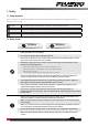
1. Safety 1.1 Safety Symbols Pay close attention to the following symbols and their meanings. Failure to follow these warnings could cause damage, injury or death. Danger • Not following these instructions may lead to serious injuries or death. Warning • Not following these instructions may lead to major injuries. Attention • Not following these instructions may lead to minor injuries. 1.
2.Introduction This product uses the 2.4GHz Third Generation AFHDS 3 protocol. The NB4 and FGr4S/FGr4 constatute a system, compatible with model cars, boats and other models. and it also supports the USB simulator function (Default enabled). 2.1 System Features AFHDS3 (third-generation automatic frequency hopping digital system) is a newly developed digital wireless system. It is compatible with single antenna bidirectional real-time data packet transmission and data stream transmission.
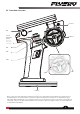
2.2 Transmitter Overview Speaker VR1 Forced shutdown button Wheel (placed at the bottom of the grip) TR3 TR4 SW1 SW3 SW2 Battery Note: If you can't shut down the transmitter properly, Please shut down the transmitter by pressing the force shutdown button on the transmitter. (Operation: pull the hand glue placed at the top of transmitter's grip or take off the whole handle glue.
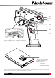
Screen VR1 Lanyard Eye TR3 TR4 SW1 Grip Trigger spring adjsustment Trigger size adjustment Battery Port USB Port (Charging), Update program, and connect the simulator interface. Power Button USB 5V 2A (Power Out) Base power button: Press for a short time to charge the battery at the transmitter handle and to charge external devices. Press 2 seconds to turn off the output of the power supply.
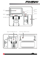
Adjustable Arm Screen TR2 Trim TR1 Trim RGB LED Power Button Trigger Position Adjustment Screw Wheel Wheel Tension Adjustment Screw 5
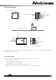
2.3 Receiver Overview Built-in antenna LED Bind Force update interface i-BUS/S.BUS CH2/CH3/CH4 CH1 S + - The transmitter is shown in a 90-degree vertical placement effect FGr4S receiver overview LED Antenna Sensors Servo CH2/CH3/CH4 Bind FGr4 receiver overview Force update interface For best signal quality,it is recommended to keep the receiver antenna up (as shown above) and away from metal when installing the FGr4S/FGr4 receivers. 2.3.
3. Getting Started Before operation, install the battery and connect the system as instructed below. 3.1 Transmitter Battery Installation Danger • Only use included batteries . Danger • Do not crush/puncture the battery, or short the external contacts. Danger • Do not open, disassemble, or attempt to repair the battery. Danger • Do not expose to excessive heat or liquids. Danger • Do not drop the battery or expose to strong shocks or vibrations. Danger • Do not use the battery if damaged.
4. Operation Instructions After setting up, follow the instructions below to operate the system. 4.1 Power On Follow the steps below to turn on the transmitter: 1. 2. Make sure that: • The battery is fully charged and installed correctly. • The receiver is installed correctly and powered on. Hold the power button until the screen turns on. 3. Connect the power supply to the receiver. Note • • Note Operate with caution in order to avoid damage or injury.
4.3 Transmitter LED Indicator This LED has five colors, red, green, blue, yellow, white and off which can be set according to user preference. You can also check the battery indicator.The transmitter LED can also be used as a power indicator. To change the LED color see the LED Strip section of this user manual. 4.4 Power Off Follow the steps below to turn off the system: 1. 2. Disconnect the receiver power first. Hold the transmitter power button until the screen turns off.
5. System Interface The main interface mainly displays information related to the model, such as transmitter voltage information, function status and so on. The display on the main interface can be customized as required, including the states and data of the main interface. Up to 8 states and data can be displayed. Main interface left slide: Channel display; right slide: Failsafe; upward slide: Timer; downward slide: System settings. If you need to change settings, click [8.7 Main Interface Shortcut].
6. Function Settings Notes: 1. The default ex-factory state of this transmitter allows the user to set the functions under CH1-CH4. To set the functions under other channels, select CH6 or CH8 in Model Settings > Channel Number Definition, and follow the steps for specific function settings. 2. Some functions are disabled by default, and you may need to click and enable the function for the setting to take effect. 3. The function menus may vary with the receiver protocols.
6.3 SUB TR Subtrim is used to change the center point for each channel. For example, if a car's wheels are slightly out of aline-ment, even when the transmitter wheel is not being touched, subtrim can be used to correct the alignment. Setup: 1. Touch the box next to the channel name to select it. When selected the box will be highlighted in green. 2. Use the + and - keys to change subtrim position. 3. Test to make sure everything is working as expected. 6.
6.6 ABS A.B.S. stands for auto breaking system. This function is used to stop the wheels from locking which can lead to loss of control or a skid. A.B.S. manages this by regulating the amount of pressure the breaks use, which is done by pumping the breaks on and off rather than a constant force. There are six sub menus for A.B.S. function setting, [Brake Return], [Delay], [Cycle Length], [Trigger Point], [Duty Cycle], and [Steering Mix].
Duty Cycle Changes the length of each pulse and the gap between them. Adjustment range is from-4 to +4 cycles. As the value changes, the length of the braking waves peaks and troughs will change independently of each other and will no longer be symmetrical. Adjusting the brake to release ratio When the period is set to "0", the ratio is 1: 1; When the period is set to "1", the ratio is 1: 2; When the period is set to "-1", the ratio is 2: 1. Steering Mix A.B.S. can be reduced automatically while turning.
6.7 Timer This function can set with a variety of timers, to generally calculate the total model run time, competition specific time spent, or transmitter run time, etc. The function can be enabled, disabled or cycle-counted by SW keys, and the timer can be reset at one touch. Please refer to [Assign] function. The timer function can be activated in three modes: Mode 1: 1.Click the [Timer Mode: Up Timer] icon. Click the right side of the corresponding function as needed.
6.8 ASSIGN The key assignment function is used to assign keys or switches to different functions for quick switch or control. The keys of SW1L, SW1R, SW2 and SW3 can enable, disable or switch CH3 to CH18 and many functions. The combo of SW2 and SW3 can adjust the values of the selected channels and functions. Note: The number of channels to control depends on [Channel Number Definition]. [Type]: Used for Normal and 2nd/3rd gear switch adjustment.
The functions of VR1-L and VR1-R are the same as above. However, the step is not adjustable. Function Assignment Icon Click the icon to enter the [Keys Assign]. In this list, you can view detailed information about the function assignment of all keys and knobs. You can directly click the corresponding button function to set the function.
6.9 Model The model functions are used to change, reset, rename, copy or customize the display and sorting of the main menu. The Noble Pro can store up to 20 models. [Select Model]: To select a model touch "Select Model", then touch a model from the list. [Name: FlySky 01]: After clicking, use the keyboard in the interface to type in a new name. [Channel Number Definition]: this function is used to select the number of channels.
If you switch to the RF standard, the model will be reset and a bind is required again. [Update RF]: The update RF function can be used to update the built-in RF module. After the firmware of the transmitter is updated, you need to update the RF when the system prompts that the RF fails or the bind of the receiver fails. • Click [Update RF], Click "Yes" after the prompt interface pops up. An update progress bar appears. Wait a few seconds. The update is completed.
FS-CPD01 FS-CVT01 FS-CTM01 FS-CPD02 FGr4 Note: If using the Classic receivers you must select the [RX Interf ace Protocol] in the [RX SET] menu and select "i-BUS", save and exit, then connect the sensor to the receiver's i-bus port. All other steps remain the same. 2.If you use an enhanced receiver, you need to set the New Port interface to ibus-in. Speed sensor (FS-CPD01, FS-CPD02) The speed sensor is applied to test the speed of the motor.
Voltage sensor (FS-CVT01) It is used to monitor the model’s battery voltage. The battery voltage can be monitored through from the transmitter. Warnings can be set. 1. Connect FS-CPD02 following the same steps as above. 2. Insert the red and black wire pins into the plug of the battery used for testing. The red wire is the positive pole and the black wire is the negative pole. When the voltage displayed on the transmitter sensor display interface is positive, the installation is successful. 3.
6.11 CH SPEED This function allows you to set the steering speed, forward speed, brake speed and response speeds of CH3 to CH8. Note: the number of channels controlled is subject to the [Channel Number Definition]. [Steering Speed]: changes the corresponding speed of the servo when the steering channel is outputting at fast speed. The minimum delay is 0.00s, and maximum delay is 10.00s. The adjustment step is 0.01s.
Channel speed - Front/Throttle This function is used to set the delay of the throttle start and return-to-center. [Go Speed]: sets the speed of throttle acceleration. [Return Speed]: sets the speed at which the throttle returns to the center position. Setup: 1. Click the option that needs to be set. This item is highlighted when selected. 2. Click the "+" or "-" icon to change the response time or the percentage of the corresponding point as required.
6.12 MIXES This function allows you to set 3 mixing functions, that is, [4WS Mixing], [Brake Mixing], and [Programming Mixes]. 4WS Mixing Used to set the wheels that control steering of the vehicle, front, rear or all four wheels. This function is applicable to crawler with steering on both front and rear wheels. By default, the front wheel steering is used in this function. [Mixing Rate]: sets the amount of mixing from the steering channel mixing to the mixed channel. The adjustment range is 0-100%.
Programming Mixes The Mixing function can be used to set the mix-control relationship between channels, containing a total of 8 groups of mixing relationships. Setup: 1. Click [Mix 1] or other mixing options as needed to enter the setting interface. 2.Click the change to . icon to enable this function. When this function is enabled, the icon will 3. Click [Master Channel], select a primary channel from the list. The primary channel will affect the secondary channel. 4.
6.14 TH Neutral Throttle Neutral creates a configurable dead zone for the throttle channel. [Forward]: How far the dead zone extends into the throttle zone. [Dead Zone]: The point at which the channel will kick in when the trigger passes the threshold. [Backward]: How far the dead zone extends into the braking zone. Setup: 1. Touch "Forward", "Dead Zone" or "Backward" to select it. 2. Use the + and - icons to to change the percentage as needed. 3. Repeat with other settings as needed. 4.
6.17 ENG CUT When Engine Cut is triggered via a button it sets the throttle channel to a predefined position. This function must be assigned to a switch/button in order to be activated. This function will reset after shutting down. You need to restart this function after turning on again. Setup: 1. Click the icon to enable this function. When this function is enabled, the icon will change to . 2.The system jumps to the [Assign] function (please refer to [6.
6.20 Beginner The beginner mode is suitable for entry level players to improve the safety of operations by limiting the amount of throttle servo. This function is hidden by default. You need to enable it manually. Setup: 1.Go to the [Custom Main Menu] menu under the [MODEL] menu bar, and select the [Beginner] check box. After selection, this function is displayed on the menu interface. 2.Find the function in the menu and click function is enabled, the icon will change to icon to enable this function.
Setup: 1.Click the • icon to enable this fu,knction. When this function is enabled, the icon will change to . If the gyroscope is not connected, this function cannot be activated, and the system prompts "The current receiver is not properly connected to the gyroscope". 2.Click [Neutral calibration]. A pop-up box will appear "Are you sure you want to enter neutral calibration? Put the steering and throttle in the neutral stationary state before entering". Click "Yes".
7 RX SET 7.1 Bind Set This function is used to adjust the transmitter to the bind state to bind it the receiver. For specific bind guidelines, see section "4.2 Bind". 7.2 Steering Force This function is used to adjust the amount of steering force when the receiver servo is steered. This function can be set when the transmitter RF Setting is set to [Mini-Z(FHSS)]. It is hidden when the RF is set to other standards. Setup: 1. Click "+" or "-" to change the percentage of steering force.
7.4 RX Interface Protocol This function is used to set the receiver output mode. When the adapted receiver is FGr4, FGr4S, FGr4P, FTr4, FTr10 and FTr16S, [Output] can be set to PWM or PPM. [Serial Protocol] can be set to i-BUS or S.BUS (please refer to [7.5 i-BUS Setting] for specific i-BUS setting). Setup: 1. Click [Receiver Interface Protocol]. 2. Click the right side of the corresponding function. Click interface.
7.5 Failsafe This function is used to protect the models and users if the receiver loses signal and therefore is no longer controllable. A list of four channels is displayed under the failsafe menu. If [Free] is displayed next to a channel, it means that after the model loses the signal, the channel will continue to maintain the last position before the failsafe kicked in.
To connect to the enhanced receiver: [SR]: one of the specifications in the servo response speed (PWM frequency is 833 Hz). [SFR]: one of the specifications in the servo response speed (PWM frequency is 1000 Hz). [Synchronization with radio frequency]: the digital signal of low frequency is synchronized with the digital signal of radio frequency. Note: the conventional servo response speed (PWM frequency) is 50-400 Hz. The delay of the whole system will be greatly improved when SR and SFR are selected.
7.8 Config PWM Converter This function allows you to configure the corresponding receiver to a PWM converter (hereinafter referred to as a secondary receiver). Setup: Note: Shut down the receiver. 1. Set the receiver to the bind state. 2. Turn on the transmitter. Enter the [Config PWM Converter] menu. Click the right side of [i-BUS to PWM].This function allows you to configure the corresponding receiver to a PWM converter (hereinafter referred to as a secondary receiver). 3.
7.11 Range Test This function is used to test whether wireless communication between the transmitter and the receiver is normal. As the actual remote control distance between transmitter and receiver is far, it is hard to test whether the radio frequency is normal by controlling a distance of several hundred meters between the transmitter and receiver in practice. Theoretically, the remote control distance in this function will be reduced to 30-40 meters.
7.14 Update Receiver After each transmitter update the receiver will need to be updated. Setup: Touch [Update Receiver]: • Some receivers such as GMR and INr4 need to be updated with "Flysky Assistant". If the transmitter has successfully coded and the connection is established, if the receiver is the latest version, a pop-up prompt will appear [The current version is the new version, no upgrade is required! ]. If the transmitter is an old version, a pop-up prompt [Are you sure to update the receiver? ].
8. SYSTEM 8.1 Language Language changes the language for the user interface. Setup: 1. Touch "Language" to enter the menu. 2. Select a language from the list. 3. Touch the icon to return to the previous menu. 8.2 Units Choose what units to use for length and temperature. Choose what units to use for length and temperature. [Length] can select metric and imperial system. The default is metric. [Temperature] can be selected in Celsius and Fahrenheit. The default is Celsius.
8.4 Sound This function is used to toggle all system sounds, including alarm sound, power-on/ power-off sounds and and adjust the volume. [Volume]: Touch volume then select the desired volume from the list. Touch the back icon to return to the previous menu. [System sound]: Click the option box on the right side of the interface. The icon will change to , indicating that the system sound is enabled.
8.7 Home-Screen Quick Access This function is used to set up the Up, Down, Left and Right quick sliding screen functions of the main interface. Users can customize the sliding screen interface according to their needs. The [Home-Screen Quick Access] can help users find setting interfaces quickly. For example, when users want to check the lap counting time after the function is enabled in the model operations, users can use this function to enter the timer interface quickly. Function settings: 1.
8.11 Stick Calibration Stick Calibration calibrates the trigger and wheel so that their center and outer positions are correct. The green bar is the channels current position and the calibrated range will be grey like the background. Calibration: 1. Move the wheel and trigger as far as they can go in each direction. 2. Touch the icon to save and return to the previous menu. 8.
9. Transmitter Specification This chapter includes specifications for NB4 transmitters, FGr4 receivers, and FGr4S receivers. 9.1 Transmitter Specification (NB4) Product model NB4 Channels 4 、6、8 (optional firmware options) Product name Model RF RF Power 2.
9.2 Receiver Specification (FGr4) Product model FGr4 RF 2.4GHz PWM 2.4GHz Protocol Distance Antenna Type Power RSSI 4 AFHDS 3 >300m (ground) single antenna(150mm) 3.5-12V Yes Data port Temperature range Humidity Range Online Update Size Weight Certification PWM/PPM/i.bus/s.bus -10℃—+60℃ 20%-95% Yes 29*22*16.2mm 8g CE,FCC ID: N4ZFGR400 9.3 Receiver Specification (FGr4S) Product model FGr4S RF 2.4GHz PWM 2.
10.
11. Certification 11.1 DoC Declaration Hereby, [Flysky Technology co., ltd] declares that the Radio Equipment [Noble(NB4),FG4] is in compliance with RED 2014/53/EU. The full text of the EU DoC is available at the following internet address: www.flysky-cn.com 11.2 CE Warning The antenna(s) used for this transmitter must be installed to provide a separation distance of at least 20 cm from all persons and must not be co-located or operating in conjunction with any other transmitter.
11.4 Appendix 1 FCC Statement This equipment has been tested and found to comply with the limits for a Class B digital device pursuant to part 15 of the FCC rules. These limits are designed to provide reasonable protection against harmful interference in a residential installation. This equipment generates, uses and can radiate radio frequency energy and, if not installed and used in accordance with the instructions, may cause harmful interference to radio communications.
www.flysky-cn.com Copyright ©2022 Flysky Technology co., ltd Release date: 2022-02-10 FCC ID: N4ZFG400 Manufacturer:ShenZhen FLYSKY Technology Co.