KCA/KCW Operation Manual CEILING MASTER
KwiKool CeilingMaster Series KCA/KCW Operation Manual Table of Contents Section I / Unit Components - Page: 3 Section II / KCA/KCW Standard Features - Page: 3 Section III /Introduction - Page: 4 Section IV / In the Package - Page: 4 Section V / Installation - Page: 4-8 Section VI / Installation Checklist - Page: 9 Section VII / Inspection & Maintenance - Page: 9 Section VIII / Troubleshooting Guide - Page: 10-11 Before installing and using your KwiKool Portable Cooling System, read this manual carefully fo
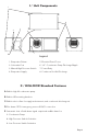
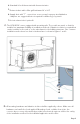
I / Unit Components 1 8 2 6 3 4 5 7 Legend 1. Evaporator Return 5. Electrical Panel Cover 2. Schreader Port 6. 1/4” Condensate Pump Discharge Nipple 3. Manual High Pressure Switch 7. Power Entry 4. Evaporator Supply 8. Condenser Hot Air Discharge II / KCA/KCW Standard Features A. Built-in high lift condensate pump B. Built-in HD mounting brackets C. Built-in duct collars for supply and return air, and condensate discharge air D. Fire alarm / EPO (emergency power off) N/O connection E.
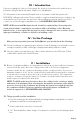
III / Introduction If you are reading this, then you have made the decision to purchase the smallest most powerful ceiling mounted unit made, KwiKool’s CeilingMaster. The information in this manual will explain how to assemble, install and operate the KCA/KCW ceiling mounted unit. Please read the complete manual before proceeding to try an install the unit. If you have any questions after reading the manual, please feel free to contact our technical support department at: 1-800-KWIKOOL (800-594-5665).
4. Standard 24 volt thermostat with thermostat wire. 5. Return air duct with a filter grill (minimum 24’ x 24”) 6. Supply duct with “T” connections as necessary for proper air distribution (dampers are suggested but not required for balancing of system) 7. Hot air exhaust duct (optional) C. The KCA/KCW comes equipped with mounting rails. These rails are made so that the installer has maximum flexibility is installation methods.
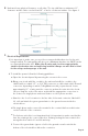
E. Unit must have physical clearance on all sides. The top shall have a minimum of 3” clearance and the sides need at least 36” of air for condenser intakes. See figure 3 F. Electrical Requirements: 1. It is important to make sure you use the recommended breaker size for the unit being installed. The rating plate will give you a Maximum breaker size (MOP) and a recommended breaker size. Make sure the wire and circuit are appropriately sized for the breaker size and unit being installed.
WARNING: All electrical work should only be performed by qualified personnel. Installation or repair to any electrical components by non-certified personnel may result in personal injury and/or damage to the unit. G. Drain Hose Connection - The KCA/KCW is equipped with a high lift internal conden- sate pump. Maximum lift is 20’. Use the provided 3/8” flexible hose and connect it to the 3/8” male connection on the unit for the evaporator coil condensate drain.
I. External Alarm Signal Connections - All KCA/KCW units are equipped with an alarm signal output relay type (Form-C, normal open dry contacts), which can be used for monitoring basic unit failure functions. Relay contactor (no connector) is closed when the following condition has occurred: 1. Condensate Tank Overflow 2. High Pressure Switch Closed 3. Low Pressure Switch Engaged 4. Cooling Function Fails The output of the relay is rated at 5A at 30VDC or 5A at 250VAC (resistive load).
VI / Installation Checklist A. Unit Installation 1. Check and make sure all screws are tight and unit is secured in place. 2. Check and make sure inlet/outlet air exhaust are clear without blockage. 3. Make suer that there is adequate condenser air ventilation. 4. Check the condensate line and make sure that the connections are secure and that the line is properly insulated. B. Wiring 1. Check and make sure the unit is properly connected to the dedicated circuit breaker. 2.
VIII/ KCA & KCW Troubleshooting Guide Fault Unit Does Not Operate Low or No Cooling No Cooling Alarm Sounding Possible Cause Possible Solution Thermostat Has No Power Check the breaker Power Interruption The unit has auto restart and will automatically restart after a 2 minute safety delay when power is restored (some 3rd party thermostats require a manual reset) Blockage of Air Duct Check ducting for any blockages for excessive bend radius’ EPO N/C Switch Open Check the EPO/Fire alarm contacts
Fault No Cooling Alarm Sounding Possible Cause Possible Solution Low Pressure Switch Actuated Potentially low on refrigerant, Call a qualified technician since this is not user serviceable Condensate Pump Overflow Check to make sure condensate line is not kinked or obstructed.
Revision 071916