
Operation Manual


TracVision M9 User’s Guide
6
Chapter 1 - Introduction
System Overview
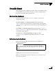
Your TracVision system is a state-of-the-art, actively stabilized
antenna system that delivers live satellite TV to your vessel’s audio/
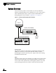
video entertainment system. A basic system is illustrated below.
Wiring diagrams are provided in “Appendix C” on page 63.
Figure 1-2 TracVision System Diagram (Basic Installation)
Antenna Unit
The antenna unit houses the antenna positioning mechanism, GPS,
LNB (low noise block), and control elements within a radome.
Weathertight connectors join the power, signal, and control cabling
from the belowdecks units.
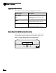
MCU
The MCU is the system’s user interface, providing access to the system
and its functions through an LCD and three buttons. The MCU also
serves as the vessel’s junction box, allowing the system to use vessel
power and supply and receive data to/from the TracVision M9.
Antenna
+24 VDC
Vessel
Power
Trac k i ng S a t A
SatB Menu SatC
Master Control Unit (MCU)
Purchased Separately
Satellite Receiver(s)
TV(s)