
Installation Instructions

Appendix
25
This appendix explains how to connect
additional receivers to the TracVision M9 system.
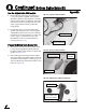
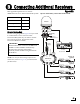
Circular Version Only
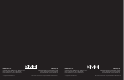
Use the wiring diagram in Figure 50 if you wish
to connect three or four receivers to the
TracVision M9 system. If you wish to connect
five or more receivers, please refer to the
TracVision M9 User’s Guide.
NOTE: You can purchase an Eagle Aspen active
multiswitch, shown in Figure 50, from KVH (order
part #72-0310).
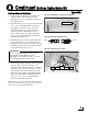
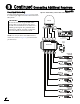
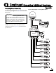
Antenna Version See
Circular Below
Linear Quad Page 26
Linear Sky Mexico Page 27
Multiswitches block a receiver’s 22 KHz tone
needed to switch satellites automatically.
Therefore, the customer will need to
manually switch satellites using the buttons
on the MCU.
IMPORTANT!
Connecting Additional Receivers
B
Figure 50 Antenna Wiring - Antenna with Circular Dual LNB
RF1
MCU
OUTPUT TO
ANTENNA
MAINTENANCE PORT RF PORT
POWER IN
+24 VDC
Vessel Power
Power In
Output to
Antenna
Antenna
RF2
Not Used
13V
SAT
Rx4
ANT
IN
Rx3
DC
20V
Rx2
Rx1
18V
SAT
Multiswitch
Power
Supply
18V
SAT
13V
SAT
Rx1
Rx2 Rx3
Rx4
Vessel
AC Ground
Grounding
Block
RF1
RF2
RF1
RF2
Data/
Power
Receiver #4
(optional)
SATELLITE IN
S-VIDEO
DIGITAL AUDIO
OUTPUT
R AUDIO VIDEO
USB
ETHERNET
L
Pr Pb Y
Satellite In
Receiver #3
(optional)
SATELLITE IN
S-VIDEO
DIGITAL AUDIO
OUTPUT
R AUDIO VIDEO
USB
ETHERNET
L
Pr Pb Y
Satellite In
Receiver #2
(optional)
SATELLITE IN
S-VIDEO
DIGITAL AUDIO
OUTPUT
R AUDIO VIDEO
USB
ETHERNET
L
Pr Pb Y
Satellite In
Receiver #1
SATELLITE IN
S-VIDEO
DIGITAL AUDIO
OUTPUT
R AUDIO VIDEO
USB
ETHERNET
L
Pr Pb Y
Satellite In