
Installation Instructions


Appendix
24
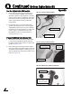
5. Secure the data/power and RF cables to the
inside rim of the baseplate, using the two
cable brackets. Secure the brackets in place
using the four M4 screws you removed
earlier (see Figure 47).
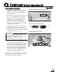
6. Attach the supplied cable exit shroud over
the cable access hole inside the baseplate,
using the two M4 screws you removed earlier
from the cover plate (see Figure 48).
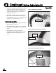
Replace the Logo Plate
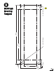
1. Attach the supplied blank logo plate using six
M4 screws (see Figure 49).
2. Discard the old logo plate, or save it in case
you need to change the cable routing in the
future.
3. The baseplate conversion process is
complete! Complete the remaining system
installation steps starting with Step 6 on
page 8.
Continued Bottom Cable Entry Kit
A
Figure 47 Cables Secured by Brackets
Figure 48 Cable Exit Shroud Installed Over Cables
Figure 49 Blank Logo Plate (No Cable Slots)
M4 Screw (x4)
M4 Screw (x2)
Cable Exit
Shroud
M4 Screw
(x6)
Blank Logo
Plate