
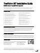
Installation Instructions

3
Before you begin, make sure you have
everything you need to complete the installation.
a. Unpack the box and ensure it contains
everything shown on the Kitpack Contents
List. Save the packaging for future use.
b. Carefully examine all of the supplied parts to
ensure nothing was damaged in shipment.
c. Gather all of the tools and materials listed
below. You will need these items to complete
the installation.
• Flat-head and Phillips-head screwdrivers
• Electric drill and 1/2" (13 mm), 5/32"
(4 mm), 3/32" (2.25 mm), and #29 bits
• 3" (80 mm) hole saw
• Socket wrenches
• 7/16" open-end wrench
• Torque wrench (Linear systems only)
• Light hammer and center punch
• Adhesive tape and scriber or pencil
• Wire strippers and terminal lug crimper
• 2 mm allen hex key (Linear systems only)
• RG-6 or RG-11 RF coax cable(s) with
Snap-N-Seal
®
F-connectors; see Step 7a
on page 9 for quantity and type required
• Augat IT1000 connector installation tool
(KVH part #19-0242)
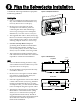
• Power cables for connecting power to the
switchplate and MCP (see Figure 2)
• Satellite TV receiver and TV (see Figure 3
for a list of validated U.S./Canadian receivers)
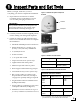
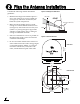
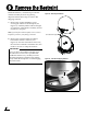
Radome
Baseplate
Figure 1: TracVision M7 System Components
Antenna
Switchplate
MCP (MultiSat Control Panel)
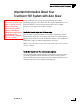
Always lift the antenna by the baseplate and
never by the radome or any portion of the
internal antenna assembly (see Figure 1).
IMPORTANT!
Figure 2: Guidelines for Power Cables
Cable Length Use Cable Gauge
< 40 ft (12 m)
14AWG (2.5mm
2
)
40-70 ft (12-21 m)
12AWG (4mm
2
)
Figure 3: KVH-Validated U.S./Canadian Receivers
* For compatibility with a Tri-Sat AutoSwitch Kit (KVH
part #72-0301-07), use model H21-200 or H20-600.
Standard-Definition Models
DIRECTV DISH Network ExpressVu
D12
D11
D10
311 4100
3100
High-Definition (HD) Models
DIRECTV DISH Network ExpressVu
H21*
H20*
211k
211
6100
Inspect Parts and Get Tools
1