
Installation Instructions

24
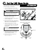
Follow these steps to set the antenna’s linear LNB
to the skew angle you noted earlier.
a. Turn off and unplug the receiver(s) and
disconnect antenna power at the switchplate.
b. Remove the antenna’s radome, if you
reinstalled it earlier in Step 8e.
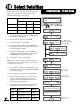
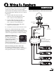
c. Locate the LNB on the back of the antenna’s
reflector (see Figure 39).
d. Using a 2 mm allen hex key, loosen the two
M4 socket set screws on the LNB choke feed.
These screws secure the LNB in place.
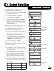
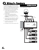
e. Adjust the LNB clockwise or counter-
clockwise until the skew arrow on the LNB
points to the skew angle you noted earlier
(see Figure 40).
f. Tighten the two M4 socket set screws to
secure the LNB in place. Apply 9 in-lbs
(1 Nm) of torque, if possible.
g. Reinstall the radome (as explained in
Steps 8e-f on page 10).
CAUTION
Disconnect power from the antenna and the
receivers before you adjust the LNB. The
antenna’s moving parts can cause injury.
M4 Socket
Set Screws
Reflector
LNB
Figure 39: Set Screws Securing the LNB to the Reflector
0˚ Skew
Positive
Skews
Negative
Skews
0
10
20
40
50
70
80
30
90
60
5
0
10
20
3
0
40
60
70
80
90
5
5
15
15
25
35
45
25
35
45
55
65
75
85
5
5
65
75
85
LNB
S
K
E
W
Choke Feed
Figure 40: LNB Skew Angle Adjustment
Be sure to keep the LNB fully inserted into the
choke feed to ensure optimum performance.
IMPORTANT!
Set the LNB Skew Angle
16
Linear Systems Only