
Operation Manual


TracVision M5/M7 User’s Guide
31
Chapter 3 - Settings
Adjusting the Skew Angle (Linear Versions)
Once you have determined the proper skew angle, follow the steps
below to adjust the antenna’s LNB skew angle.
TIP: Refer to “Displaying the Calculated Skew Angle” on page 30 to
determine the skew angle for the currently selected satellite. If you wish to
determine the average skew angle for two or three satellites, see “European
Tri-Sat Mode Setup” on page 48 or “Linear Dual-Sat Mode Setup” on
page 50.
TIP: For information on how skew works, see “LNB Skew Angle” on
page 8.
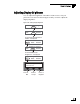
1. Using a Phillips-head screwdriver, remove the screws
securing the radome. Then remove the radome and set
it aside in a safe place.
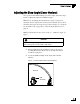
2. Locate the LNB assembly on the back of the antenna
reflector.
Figure 3-3 Location of LNB on Back of Antenna Reflector
CAUTION
To avoid bodily injury, be sure to turn off the antenna and
disconnect power to all wired components.
Reflector
LNB
Assembly