TracVision M5/M7 TracVision M5/M7 Control Panel Configuration quick reference guide flip here to view User’s Guide TracVision MultiSat Control Panel Menu
TracVision M7 with Auto Skew Important Information About Your System Important Information About Your TracVision M7 System with Auto Skew ® Note: Not all TracVison M7 systems include Auto Skew. If you are unsure whether your linear TracVision M7 system includes automatic or manual skew adjustment, please refer to the documentation supplied with your system.
MultiSat Control Panel Menu Quick Reference Guide Tracking Menu Install Satellite? Yes Next Return Circular or Linear? Cir Lin Cancel Set Sat Switch Type? Yes Next Return Auto or Manual? Auto Manual Cancel Automatic Satellite Switching Restart Antenna? Yes Next Return Select a DIRECTV mode Service=DISH? Yes Next Cancel Select a DISH Network mode Service=ExpressVu? Yes Next Cancel Select ExpressVu Service=Custom? Yes Next Cancel Select 1 or 2 satellites from the library Yes Manual Satel
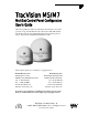
TracVision M5/M7 User’s Guide TracVision M5/M7 MultiSat Control Panel Configuration User’s Guide This user’s guide provides all of the basic information you need to operate, set up, and troubleshoot the TracVision M5/M7 satellite TV antenna system. For detailed installation information, please refer to the TracVision M5/M7 Installation Guide. Please direct questions, comments, or suggestions to: KVH Industries, Inc.
TracVision and KVH are registered trademarks of KVH Industries, Inc. The unique light-colored dome with dark contrasting base is a registered trademark of KVH Industries, Inc. DVB (Digital Video Broadcasting) is a registered trademark of the DVB Project. DIRECTV is an official trademark of DIRECTV, Inc. DISH Network is an official trademark of EchoStar Communications Corporation. ExpressVu is a property of Bell ExpressVu, a wholly owned subsidiary of Bell Satellite Services.
TracVision M5/M7 User’s Guide Table of Contents Table of Contents 1 Introduction Using this Manual ..............................................................................3 System Overview...............................................................................5 Circular and Linear Versions..............................................................8 2 Operation Receiving Satellite TV Signals .........................................................13 Turning the System On/Off ............
TracVision M5/M7 User’s Guide Table of Contents 3 Settings (Continued) European Tri-Sat Mode Setup..........................................................48 Linear Dual-Sat Mode Setup............................................................50 Selecting Automatic or Manual Satellite Switching.........................53 Resetting to Factory Default Settings ..............................................54 Restarting the TracVision System....................................................
TracVision M5/M7 User’s Guide Chapter 1 - Introduction 1. Introduction This chapter provides a basic overview of this manual and your TracVision system. Contents Using this Manual.............................................................. 3 System Overview............................................................... 5 Circular and Linear Versions..............................................
TracVision M5/M7 User’s Guide Chapter 1 - Introduction Using this Manual This manual provides complete operation, setup, and troubleshooting information for your TracVision system, as well as wiring diagrams for various TracVision M5/M7 system configurations. Who Should Use This Manual The user should refer to the “Operation” chapter to learn how to operate the system.
TracVision M5/M7 User’s Guide Chapter 1 - Introduction Typographical Conventions This manual uses the following typographical conventions: Text Example Description ### Text in brackets or the pound sign (#) indicates a variable portion of the MultiSat Control Panel (MCP) display MultiSat Control Panel (MCP) Interface Conventions When instructions indicate to select a specific MCP menu option, press the MCP button located directly beneath the menu option.
TracVision M5/M7 User’s Guide Chapter 1 - Introduction System Overview Your TracVision M5/M7 system is a state-of-the-art, actively stabilized antenna system that delivers live satellite TV to your vessel’s audio/video entertainment system. A basic system is illustrated below.
TracVision M5/M7 User’s Guide Chapter 1 - Introduction System Components The TracVision M5/M7 system includes the following components: Antenna Unit The antenna unit houses the antenna positioning mechanism, LNB (low noise block), and control elements within a radome. Weathertight connectors join the power, signal, and control cabling from the belowdecks units. Switchplate The switchplate controls power to the antenna via the On/Off switch.
TracVision M5/M7 User’s Guide Chapter 1 - Introduction System Features Your TracVision M5/M7 system uses integrated DVB technology to quickly acquire and track the correct satellite, switch between your selected satellites, and send TV signals to the receiver. In-motion Tracking The TracVision system uses a state-of-the-art actively stabilized antenna.
TracVision M5/M7 User’s Guide Chapter 1 - Introduction Circular and Linear Versions Your TracVision system is configured to receive either circularly polarized satellite signals (e.g., North America) or linearly polarized satellite signals (e.g., Europe or Latin America). Figure 1-3 illustrates the difference between these two polarizations.
TracVision M5/M7 User’s Guide Chapter 1 - Introduction The correct skew setting varies depending on your geographic location, since the orientation of your antenna to the satellite changes as you move. For example, if your antenna is tracking the PAS 9 satellite for Sky Mexico programming, the ideal skew setting ranges from +30 to +70, depending upon your location within the satellite’s coverage area (see Figure 1-5).
TracVision M5/M7 User’s Guide Chapter 2 - Operation 2. Operation This chapter explains everything you need to know to operate the TracVision system. Contents Receiving Satellite TV Signals ......................................... 13 Turning the System On/Off .............................................. 14 Changing Channels and Switching Between Satellites (Circular Versions) ........................................... 15 Changing Channels and Switching Between Satellites (Linear Versions)..............
TracVision M5/M7 User’s Guide Chapter 2 - Operation Receiving Satellite TV Signals Television satellites are located in fixed positions above the Earth’s equator and beam TV signals down to certain regions of the planet (not worldwide). To receive TV signals from a satellite, you must be located within that satellite’s unique coverage area. TIP: For your convenience, KVH provides links to several websites that offer satellite coverage information. Simply visit our website at www.kvh.com/ footprint.
TracVision M5/M7 User’s Guide Chapter 2 - Operation Turning the System On/Off You can turn the system on or off using the switchplate. Turning On the System Follow the steps below to turn on your TracVision system. IMPORTANT! Avoid turning the vessel or changing channels for one minute after turning on the system. 1. Make sure the antenna has a clear view of the sky. 2. Turn on your satellite TV receiver and TV. 3. Set the switchplate’s Power switch to the On (|) position.
TracVision M5/M7 User’s Guide Chapter 2 - Operation Changing Channels and Switching Between Satellites (Circular Versions) During installation, your TracVision system should have been set up to track the satellite(s) of your choice and the channel guides for your selected satellite service should have been downloaded. Since some channels might be located on another satellite, changing channels might require switching between satellites.
TracVision M5/M7 User’s Guide Chapter 2 - Operation DISH 1000 Automatic Mode - Preferred for One or Two Receivers The antenna switches between satellites automatically as you change channels using the primary receiver’s remote control. The primary receiver is the receiver connected to RF1 (see Figure 2-6 and Figure 2-7). If an optional secondary receiver is connected, you can use its remote control to switch between the channels on the currently selected satellite.
TracVision M5/M7 User’s Guide Chapter 2 - Operation DISH 1000 Manual Mode - Required for Three or More Receivers Since multiswitches interfere with communications between the receivers and the antenna, the system must be set up in Manual mode when three or more receivers are installed. When Manual mode is enabled, you can switch between your selected satellites using the buttons on the front of the MCP (see Figure 2-8 and Figure 2-9).
TracVision M5/M7 User’s Guide Chapter 2 - Operation Dual-Sat Mode - Required for all DISH 500, ExpressVu, DIRECTV, and Custom Dual-Sat Setups Dual-Sat Mode is used with several service configurations. Figure 2-10 lists each Dual-Sat service configuration, the satellites tracked for each service, and available satellite switching modes.
TracVision M5/M7 User’s Guide Chapter 2 - Operation Dual-Sat Automatic Mode - Preferred Mode for One or Two Receivers* The antenna switches between satellites automatically while you change channels using the primary receiver’s remote control. The primary receiver is the receiver connected to the antenna’s RF1 cable (see Figure 2-11 and Figure 2-12). If an optional secondary receiver is connected, you can use its remote control to switch between the channels on the currently selected satellite.
TracVision M5/M7 User’s Guide Chapter 2 - Operation Dual-Sat Manual Mode - Required for Three or More Receivers and All Custom Dual-Sat Setups Circular TracVision M5/M7 systems with three or more receivers require the use of a multiswitch. Since multiswitches interfere with communications between the receivers and the antenna, the system must be set up in Manual mode. When manual mode is enabled, you can use the receiver’s remote control to change channels on the currently selected satellite.
TracVision M5/M7 User’s Guide Chapter 2 - Operation Changing Channels and Switching Between Satellites (Linear Versions) During installation, your TracVision system should have been set up to track the satellite(s) of your choice and the channel guides for your selected satellite service should have been downloaded. Since some channels might be located on another satellite, changing channels might require switching between satellites.
TracVision M5/M7 User’s Guide Chapter 2 - Operation Automatic Satellite Switching The TracVision system can switch between satellites automatically as long as the primary receiver is set up for DiSEqC communicatons and a multiswitch is not installed. With DiSEqC set up, the primary receiver sends satellite switching commands to the antenna as necessary when you change channels using the primary receiver’s remote control.
TracVision M5/M7 User’s Guide Chapter 2 - Operation Manual Satellite Switching If the TracVision system includes a multiswitch, you can use the receivers’ remote controls to change channels on the currently selected satellite. If you need to switch satellites, simply use the buttons on the front of the MCP (see Figure 2-17 and Figure 2-18).
TracVision M5/M7 User’s Guide Chapter 2 - Operation Receiver Requirements This section lists U.S. and Canadian circular receiver models that are compatible with the TracVision M5/M7 system and explains linear and circular receiver setup requirements. Circular Receiver Compatibility To ensure compatibility with your TracVision M5/M7 system, be sure to use a KVH-validated receiver for your selected service type (see Figure 2-19). Figure 2-19 KVH-Validated U.S.
TracVision M5/M7 User’s Guide Chapter 2 - Operation DISH Network/ExpressVu Receiver Configuration If your TracVision M5/M7 system is set up for DISH Network or ExpressVu service, your receiver(s) should have also been configured during installation. In most cases, you do not need to reconfigure your receiver(s). However, Figure 2-20 lists special scenarios that require DISH Network/ExpressVu receiver configuration. Figure 2-20 Receiver Configuration Requirements Receiver Configuration is Required When...
TracVision M5/M7 User’s Guide Chapter 2 - Operation Product Care Please consider the following antenna care guidelines for maintaining peak performance: 26 • Periodically wash the exterior of the antenna dome with fresh water and mild detergent. Avoid harsh cleansers and volatile solvents (such as acetone) and do not spray the dome directly with high-pressure water. • If you wish to paint the dome, use only non-metallic automotive paint without a primer coat.
TracVision M5/M7 User’s Guide Chapter 3 - Settings 3. Settings This chapter contains information on system settings and how to modify them. Contents Updating Latitude and Longitude Data ............................ 29 Displaying the Calculated Skew Angle ............................ 30 Adjusting the Skew Angle (Linear Versions).................... 31 Setting Sleep Mode ......................................................... 35 Setting Instant On...........................................................
TracVision M5/M7 User’s Guide Chapter 3 - Settings Updating Latitude and Longitude Data Use the flowchart in Figure 3-1 if you wish to update your latitude and longitude data. TIP: For your convenience, you can determine your approximate latitude and longitude using the Position Grids provided in Appendix B on page 75. Figure 3-1 Updating Latitude and Longitude Data Menu Install Satellite? Yes Next Return Select Next until “Operations Mode?” is displayed.
TracVision M5/M7 User’s Guide Chapter 3 - Settings Displaying the Calculated Skew Angle Use the flowchart in Figure 3-2 to display the average skew angle for your selected satellites. If just one satellite is configured for tracking, that satellite’s skew angle is displayed. IMPORTANT! An accurate skew angle reading requires current latitude and longitude data.
TracVision M5/M7 User’s Guide Chapter 3 - Settings Adjusting the Skew Angle (Linear Versions) Once you have determined the proper skew angle, follow the steps below to adjust the antenna’s LNB skew angle. TIP: Refer to “Displaying the Calculated Skew Angle” on page 30 to determine the skew angle for the currently selected satellite. If you wish to determine the average skew angle for two or three satellites, see “European Tri-Sat Mode Setup” on page 48 or “Linear Dual-Sat Mode Setup” on page 50.
TracVision M5/M7 User’s Guide Chapter 3 - Settings 3. Using a 2 mm allen hex key, loosen the two M4 socket set screws securing the LNB. The location of the screws varies according to TracVision model; refer to Figure 3-4 or Figure 3-5.
TracVision M5/M7 User’s Guide Chapter 3 - Settings 4a. TracVision M5 Only - Adjust the LNB clockwise or counter-clockwise, until the skew arrow on the LNB points to the skew angle that you determined earlier. Due to label constraints, if the skew angle is greater than +15°, you need to subtract 180 to get the equivalent negative skew angle and set the LNB to that angle instead. For example, if the skew angle is determined to be +30°, set the skew to -150°.
TracVision M5/M7 User’s Guide Chapter 3 - Settings 4b. TracVision M7 Only - Adjust the LNB clockwise or counter-clockwise, until the skew arrow on the LNB points to the skew angle that you determined earlier. IMPORTANT! Be sure to keep the LNB fully inserted in the choke feed to ensure optimum performance.
TracVision M5/M7 User’s Guide Chapter 3 - Settings Setting Sleep Mode When the vessel has come to a stop and holds its position for one minute (e.g., at a dock), the antenna unit enters Sleep Mode, which locks the antenna in place to conserve power. As soon as the vessel moves beyond a 1° - 2° window or the signal level changes significantly, Sleep Mode automatically turns off and the system begins tracking the satellite again (or enters Search Mode to find the satellite).
TracVision M5/M7 User’s Guide Chapter 3 - Settings Setting Instant On When Instant On is enabled, the antenna can immediately receive signals if the vessel has not moved since the antenna was last shut off. However, if the system is turned off, and then the vessel moves after last acquiring the satellite via Instant On, the antenna will undergo its standard initialization process once it is turned back on. This results in a brief delay.
TracVision M5/M7 User’s Guide Chapter 3 - Settings Adjusting Display Brightness You can adjust the brightness of the MCP’s LCD screen to suit your preferences. Use the flowchart in Figure 3-10 if you wish to adjust the display brightness. Figure 3-10 Setting Display Brightness Menu Install Satellite? Yes Next Return Select Next until “Operations Mode?” is displayed. Operations Mode? Yes Next Return Get Antenna Status? Yes Next Return Select Next until “Set Brightness?” is displayed.
TracVision M5/M7 User’s Guide Chapter 3 - Settings DISH Network/ExpressVu Setup This section explains how to configure the TracVision system for DISH 1000, DISH 500, or ExpressVu use. For operation instructions and additional information on DISH modes, refer to “Changing Channels and Switching Between Satellites (Circular Versions)” on page 15. Step 1 - Configure the TracVision System Use the flowchart in Figure 3-11 on page 39 to configure the TracVision system for DISH Network service.
TracVision M5/M7 User’s Guide Chapter 3 - Settings Figure 3-11 Configuring DISH Network Menu Install Satellite? Yes Next Return Circular or Linear? Cir Lin Return Service= DIRECTV? Yes Next Cancel Service= DISH? Yes Next Cancel Mode= DISH 1000/61? Yes Next Cancel Yes Set Lat/Long? Next Return Press - or + to toggle each digit to the desired value, then press Enter to accept each digit.
TracVision M5/M7 User’s Guide Chapter 3 - Settings Figure 3-12 Configuring ExpressVu Menu Install Satellite? Yes Next Return IMPORTANT: Choose Auto for configurations if 1 or 2 receivers are connected; choose Manual if 3 or more receivers are connected.
TracVision M5/M7 User’s Guide Chapter 3 - Settings Step 2 - Configure the Receiver(s) NOTE: If you are connecting multiple receivers, repeat this process for each additional receiver. You will need to connect each receiver, one at a time, to the RF1 cable and perform the steps below. Then, once you have completed this process for each receiver, you can reconnect them as desired. 1. Ensure the receiver you wish to configure is connected to the TracVision system’s RF1 cable. 2.
TracVision M5/M7 User’s Guide Chapter 3 - Settings 7. Refer to the tables in Figures 3-15 through Figure 3-18 (on the following page) to verify the values on your TV screen match those required for your selected satellite TV service. If your values do not match, turn off the TracVision system, then turn it back on and repeat Steps 3-6.
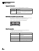
TracVision M5/M7 User’s Guide Chapter 3 - Settings Figure 3-18 ExpressVu Expected Check Switch Results on TV Screen* Port 1 1 2 2 Satellite 91 91 82 82 Trans Odd Even Odd Even Status Reception Verified Switch SW21 *NOTE: If you installed just one ExpressVu satellite, the TV screen will display an error message instead; this is normal. 8. Exit the menu and allow the receiver to download the program guide.
TracVision M5/M7 User’s Guide Chapter 3 - Settings DIRECTV Dual-Sat Mode Setup This section explains how to configure the TracVision system to track the DIRECTV 101 and 119 satellites. Use the flowchart in Figure 3-19 to configure the TracVision system for DIRECTV Dual-Sat Mode. For operation instructions, refer to “Changing Channels and Switching Between Satellites (Circular Versions)” on page 15.
TracVision M5/M7 User’s Guide Chapter 3 - Settings Circular Custom Dual-Sat Setup The following instructions explain how to configure the TracVision system to track any two satellites of your choice from the circular antenna’s circular satellite library (shown in Figure 3-20 on page 46). For operation instructions, refer to “Changing Channels and Switching Between Satellites (Circular Versions)” on page 15.
TracVision M5/M7 User’s Guide Chapter 3 - Settings Figure 3-20 Circular Satellite Library Satellite Service Satellite Location Installation Name AsiaSat 4 122.2° E ASIASAT* 72.0° W DSS_72 101.0° W DSS_101 110.0° W DSS_110* 119.0° W DSS_119 95.0° W GALAXY3CN* 61.5° W ECHO_61 110.0° W ECHO_110 119.0° W ECHO_119 129.0° W ECHO_129 91.0° W EXPRESSTV 82.
TracVision M5/M7 User’s Guide Chapter 3 - Settings Use the flowchart in Figure 3-21 to configure the TracVision system for your custom pair of satellites (or single satellite). Figure 3-21 Configuring Custom Dual-Sat Mode Menu Install Yes Next Cancel Press Next until your choice for Satellite A is displayed, then press Yes.
TracVision M5/M7 User’s Guide Chapter 3 - Settings European Tri-Sat Mode Setup This section explains how to configure the TracVision system to track three satellites within predefined linear satellite groups for use in European locations (see Figure 3-22). For operation instructions, refer to “Changing Channels and Switching Between Satellites (Linear Versions)” on page 21.
TracVision M5/M7 User’s Guide Chapter 3 - Settings Figure 3-23 Configuring European Tri-Sat Mode Menu Install Satellite? Yes Next Return Circular or Linear? Cir Lin Cancel Trisat Mode? Yes No Cancel Install Europe WB? Yes Next Cancel Press Next until your desired Trisat Group is displayed, then press Yes.
TracVision M5/M7 User’s Guide Chapter 3 - Settings Linear Dual-Sat Mode Setup This section explains how to configure the TracVision system to track any two satellites from the antenna’s linear satellite library (shown in Figure 3-24). For operation instructions, refer to “Changing Channels and Switching Between Satellites (Linear Versions)” on page 21. Figure 3-24 Linear Satellite Library Satellite Location Satellite Installation Name 26.0° E Arabsat ARABSAT 19.2° E Astra 1 ASTRA1 28.
TracVision M5/M7 User’s Guide Chapter 3 - Settings Step 1 - Configure the Satellites Use the flowchart in Figure 3-25 to configure the TracVision system for linear Dual-Sat Mode. NOTE: Be sure to record the skew angle (the average skew for both satellites) reported during this procedure. You will need this information to adjust the TracVision system’s skew angle.
TracVision M5/M7 User’s Guide Chapter 3 - Settings Step 2 - Adjust the LNB Skew Angle Now that you have installed the desired satellites and recorded the skew angle, you need to adjust the antenna’s LNB skew angle to optimize signal reception. Follow the instructions in “Adjusting the Skew Angle (Linear Versions)” on page 31 to adjust the skew angle. NOTE: To enable automatic satellite switching, the receiver must be set up to match the TracVision system’s satellite settings.
TracVision M5/M7 User’s Guide Chapter 3 - Settings Selecting Automatic or Manual Satellite Switching When your TracVision system was configured, the satellite switching method (automatic or manual) was also selected. However, you can use the flowchart in Figure 3-26 to change the satellite switching method for your selected service, if desired.
TracVision M5/M7 User’s Guide Chapter 3 - Settings Resetting to Factory Default Settings Use the flowchart in Figure 3-27 if you wish to reset the TracVision system to the factory default satellite service (DIRECTV Dual-Sat Mode) and LCD brightness settings. Figure 3-27 Resetting to Factory Default Settings Menu Install Satellite? Yes Next Return Select Next until “Operations Mode?” is displayed.
TracVision M5/M7 User’s Guide Chapter 3 - Settings Restarting the TracVision System Use the flowchart in Figure 3-28 if you wish to restart the TracVision system. Figure 3-28 Restarting the TracVision System Menu Install Satellite? Yes Next Return Select Next until “Restart Antenna?” is displayed.
TracVision M5/M7 User’s Guide Chapter 4 - Troubleshooting 4. Troubleshooting This chapter identifies potential basic problems along with their possible causes and solutions. It also explains how to get technical support. Contents Five Simple Checks ......................................................... 59 Troubleshooting Matrix.................................................... 60 Causes and Remedies for Operational Issues ................. 61 Technical Support.........................................
TracVision M5/M7 User’s Guide Chapter 4 - Troubleshooting Five Simple Checks If you are experiencing a problem receiving satellite TV with your TracVision system, perform the five simple checks below. TIP: You can also try resetting the satellite TV receiver. Turn off and unplug the receiver, wait one minute, then plug it back in and turn it back on. Can the antenna see the satellite? The antenna requires an unobstructed view of the sky to receive satellite TV signals.
TracVision M5/M7 User’s Guide Chapter 4 - Troubleshooting Troubleshooting Matrix The troubleshooting matrix in Figure 4-1 identifies potential operational symptoms and their causes and remedies. “Causes and Remedies for Operational Issues” on page 61 contains detailed information on the causes and remedies listed below.
TracVision M5/M7 User’s Guide Chapter 4 - Troubleshooting Causes and Remedies for Operational Issues This section addresses the most common operational issues that can affect the performance of the TracVision M5/M7 system. If your TracVision system requires service, you can visit any KVH-authorized dealer or distributor for assistance. To find a KVH-authorized dealer near you, visit www.kvh.com/wheretogetservice.
TracVision M5/M7 User’s Guide Chapter 4 - Troubleshooting Satellite Coverage Issue Television satellites are located in fixed positions above the Earth’s equator and beam TV signals down to certain regions of the planet (not worldwide). To receive TV signals from a satellite, you must be located within that satellite’s unique coverage area. TIP: For your convenience, KVH provides links to several websites that offer satellite coverage information. Simply visit our website at www.kvh.com/ footprint.
TracVision M5/M7 User’s Guide Chapter 4 - Troubleshooting Radar Interference The TracVision M5/M7 antenna must be kept out of line with nearby radars, as their energy levels might overload the antenna’s front-end circuits. Refer to the TracVision M5/M7 Installation Guide for details, or visit any KVH-authorized dealer or distributor for assistance. To find a KVH-authorized dealer near you, visit www.kvh.com/ wheretogetservice.
TracVision M5/M7 User’s Guide Chapter 4 - Troubleshooting Loose RF Connectors KVH recommends periodically checking the system’s cable connections. A loose RF connector can reduce signal quality or prevent automatic satellite switching using the receiver’s remote control. Refer to the TracVision M5/M7 Installation Guide for complete system wiring information, or visit any KVH-authorized dealer or distributor for assistance. To find a KVH-authorized dealer near you, visit www.kvh.com/wheretogetservice.
TracVision M5/M7 User’s Guide Chapter 4 - Troubleshooting Technical Support The TracVision M5/M7 antenna is a sophisticated electronic device. KVH-authorized technicians have the specialized tools and expertise necessary to diagnose and repair a system fault. Therefore, if you experience any operating problem or require technical assistance, please call or visit your local authorized TracVision dealer or distributor. To find a KVH-authorized dealer near you, visit www.kvh.com/wheretogetservice.
TracVision M5/M7 User’s Guide Appendix A - Advanced Settings and Functions Appendix A Advanced Settings and Functions This appendix contains information on advanced settings and functions. This information should only be utilized by KVH-authorized technicians. Contents Manually Control the Antenna ......................................... 69 Updating Satellite Frequency Data .................................. 70 Configuring Satellite Settings..........................................
TracVision M5/M7 User’s Guide Appendix A - Advanced Settings and Functions Manually Controlling the Antenna Use the flowchart in Figure A-1 if you wish to control the antenna manually. NOTE: If you are performing this procedure as part of the satellite frequency scan update procedure, be sure to select “NO” at the “Make Antenna Track?” screen. NOTE: Azimuth is referenced to forward, not a true compass heading. TIP: Once you have finished positioning the antenna, the system will revert to automatic control.
TracVision M5/M7 User’s Guide Appendix A - Advanced Settings and Functions Updating Satellite Frequency Data If the antenna is unable to find a satellite, or if you are unable to receive certain channels, the satellite’s frequency data might have changed. The satellite frequency scan feature allows you to update the frequency data of any satellite stored in the system’s library.
TracVision M5/M7 User’s Guide Appendix A - Advanced Settings and Functions 5. Use the flowchart in Figure A-2 to scan the frequency data of the selected satellites. TIP: If you know the satellite configuration data, you can configure the satellite without scanning frequency data (see “Configuring Satellite Settings” on page 72). TIP: Scanning satellite frequencies might take up to 10 minutes.
TracVision M5/M7 User’s Guide Appendix A - Advanced Settings and Functions Configuring Satellite Settings Use the flowchart in Figure A-3 to configure one of the satellites selected for tracking. TIP: Linear satellites use the following polarization/band combinations: vertical high, vertical low, horizontal high, and horizontal low. Circular satellites use the following polarization/band combinations: right and left.
TracVision M5/M7 User’s Guide Appendix A - Advanced Settings and Functions Displaying Software Version Information Use the flowchart in Figure A-4 if you wish to display software version information. Figure A-4 Displaying Software Version Information Menu Install Satellite? Yes Next Return Select Next until “Operations Mode?” is displayed. Operations Mode? Yes Next Return Get Antenna Status? Yes Next Return Get system errors? Yes Next Return Yes Get Version? Next Return CP #.
TracVision M5/M7 User’s Guide Appendix A - Advanced Settings and Functions Displaying the Antenna Serial Number Use the flowchart in Figure A-5 if you wish to view the antenna serial number. Figure A-5 Displaying Antenna Serial Number Menu Install Satellite? Yes Next Return Select Next until “Operations Mode?” is displayed. Operations Mode? Yes Next Return Get Antenna Status? Yes Next Return Get system errors? Yes Next Return Select Next until “Get serial number?” is displayed.
TracVision M5/M7 User’s Guide Appendix B - Position Grids Appendix B Position Grids This appendix contains European and North American position grids for determining your approximate latitude and longitude. Contents European Position Grid .................................................... 77 North American Position Grid ..........................................
TracVision M5/M7 User’s Guide Appendix B - Position Grids European Position Grid If you wish to determine your approximate latitude and longitude, use the position grid and table in Figure B-1.
TracVision M5/M7 User’s Guide Appendix B - Position Grids North American Position Grid If you wish to determine your approximate latitude and longitude, use the position grid and table in Figure B-2.
TracVision M5/M7 User’s Guide Appendix C - Wiring Diagrams Appendix C Wiring Diagrams This appendix provides receiver wiring diagrams for basic configurations. Wiring diagrams vary according to the number of receivers installed and the TracVision system configuration (circular/ linear and dual/quad-output). For installation instructions, refer to the TracVision M5/M7 Installation Guide. Contents Wiring Diagram for One or Two Receivers ......................
TracVision M5/M7 User’s Guide Appendix C - Wiring Diagrams Wiring Diagram for One or Two Receivers Antenna Data Power RF2 RF1 Switchplate + – + – RJ 22 Maintenance Power Terminal Strip DB9 OR +12 VDC Vessel Power Antenna Unit RF Port Power In MCP + – + HDTV CONTROL ANTENNA UNIT RF PORT FUSE POWER IN +/– Grounding Block (Circular/Sky Mexico Systems Only) Vessel AC Ground RF2 TONE DETECT + RF1 Receiver #1 Satellite In OFF-AIR IN COMPONENT OUT SATELLITE IN CAUTION VIDEO OUT AC 120V,
TracVision M5/M7 User’s Guide Appendix C - Wiring Diagrams Circular Versions Only Wiring Diagram for Three or Four Receivers (Circular Versions)* Antenna Data Power RF2 RF1 Switchplate + – + – RJ 22 Maintenance Power Terminal Strip DB9 OR +12 VDC Vessel Power Antenna Unit RF Port Power In MCP + – + HDTV CONTROL ANTENNA UNIT RF PORT TONE DETECT FUSE + POWER IN +/– Vessel AC Ground Receiver #4 Satellite In OFF-AIR IN COMPONENT OUT SATELLITE IN RF1 CAUTION AC 120V, 60 Hz S-VIDEO OUT
TracVision M5/M7 User’s Guide Appendix C - Wiring Diagrams Linear Quad-output Versions Only Wiring Diagram for Three or Four Receivers (Linear Quad-output Versions) Antenna Data Power Switchplate RF1 RF2 + – RF3 RF4 + – RJ 22 Maintenance Power Terminal Strip DB9 OR +12 VDC Vessel Power Antenna Unit RF Port Power In MCP + – + HDTV CONTROL ANTENNA UNIT TONE DETECT FUSE + POWER IN +/– Receiver #1 Satellite In OFF-AIR IN RF PORT COMPONENT OUT SATELLITE IN CAUTION VIDEO OUT AC 120V, 60
KVH Industries, Inc. 50 Enterprise Center Middletown, RI 02842-5279 U.S.A. Phone: +1 401 847-3327 Fax: +1 401 849-0045 E-mail: info@kvh.com Internet: www.kvh.com © Copyright 2008 KVH Industries Inc. KVH Europe A/S Kokkedal Industripark 2B 2980 Kokkedal Denmark Phone: +45 45 160 180 Fax: +45 45 160 181 E-mail: info@kvh.dk Internet: www.kvh.com KVH, TracVision, and TracPhone are registered trademarks of KVH Industries Inc. KVH Industries, Inc. 50 Enterprise Center Middletown, RI 02842-5279 U.S.A.