
Installation Instructions

11
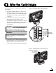
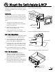
Follow these steps to connect the switchplate to
the antenna.
a. First dress the data and power cables from
the antenna. Strip back the insulation of each
wire approximately 1/4" (6 mm) and gently
twist each wire to ensure a good electrical
connection.
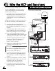
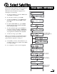
b. Connect the data cable from the antenna to
the terminal board on the back of the
switchplate (see Figure 22). Be sure to match
the wire colors with the terminal board label.
Tighten the terminal screws to secure all
wires in place.
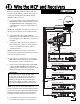
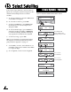
c. Connect the power cable from the antenna to
the switchplate’s power output terminals (see
Figure 23). Later, you will also connect a
power cable from these terminals to the MCP.
Brown/White
White/Brown
Orange/White
White/Orange
Gray/White
White/Gray
Antenna
Data Cable
Body/Stripe
Figure 22: Switchplate Wiring - Antenna Data Cable
The diagram refers to wires by body color/
stripe color. For example, “Brown/White”
means the brown wire with the white stripe.
IMPORTANT!
Do not connect the data cable’s drain wire
(shield) to anything. You can simply snip it
from the cable.
IMPORTANT!
+12 VDC (Red)
Ground (Black)
Antenna Power Cable
+
–
Figure 23: Switchplate Wiring - Antenna Power Cable
Wire the Switchplate
9