Installation Guide TracVision M5 TracVision M5 Control Panel Configuration
TracVision M5 Installation Guide MultiSat Control Panel (MCP) Configuration These instructions explain how to install the TracVision M5 satellite TV antenna system on a vessel. Complete instructions on how to use the system are provided in the User’s Guide. Installation Steps 1. Inspect Parts and Get Tools ...............3 10. Wire the MCP and Receivers........... 12 2. Plan the Antenna Installation ............4 11. Connect Power .................................. 14 3.
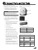
1 Inspect Parts and Get Tools Before you begin, make sure you have everything you need to complete the installation. Figure 1: TracVision M5 System Components Antenna a. Unpack the box and ensure it contains everything shown on the Kitpack Contents List. Save the packaging for future use. Radome IMPORTANT! Always lift the antenna by the baseplate and never by the radome or any portion of the internal antenna assembly (see Figure 1). b.
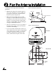
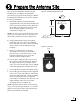
2 Plan the Antenna Installation Consider the following antenna installation guidelines: • • Figure 4: Blockage from Obstruction Minimize blockage. The antenna requires a clear view of the sky to receive satellite TV (see Figure 4). The fewer obstructions, the better the system will perform. Make sure the mounting surface is wide enough to accommodate the antenna’s base (see Figure 5). Also make sure it is flat, level (within ±1°), strong enough to support the antenna’s weight (30 lbs, 13.
3 Plan the Belowdecks Installation Consider the following belowdecks equipment installation guidelines. Figure 6: Switchplate Dimensions Top View Switchplate • Select a switchplate mounting location in a dry, well-ventilated area belowdecks away from any heat sources or salt spray. • Be sure to leave enough room at the switchplate’s rear panel for connecting the cables and maintaining a service loop (see Figure 6 for switchplate dimensions). • The supplied data cable is 50 ft (15 m) long.
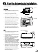
4 Prepare the Belowdecks Sites Once you have identified suitable mounting sites for the switchplate and MCP, follow these steps to prepare the sites for installation. Figure 8: Switchplate Mounting Holes Layout 3.82" (97 mm) .32" (8 mm) Switchplate a. Using the switchplate mounting template provided at the end of this manual, mark and cut out a hole in the mounting surface to accommodate the switchplate (see Figure 8). b. Using the same template, mark the locations for the four switchplate mounting holes.
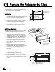
5 Prepare the Antenna Site Once you have identified a suitable antenna mounting site, according to the guidelines provided on page 4, follow these steps to drill the mounting holes and cable access hole to prepare the site for installation. a. Unfold the antenna mounting template (supplied in the Customer Welcome Kit) and place it onto the mounting surface. Make sure the “FWD” (forward) arrow points toward the bow and is parallel to the vessel’s centerline (see Figure 11).
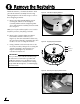
6 Remove the Restraints Inside the antenna, a foam block and two bolts prevent the antenna assembly from moving during shipment. Follow these steps to remove these shipping restraints. a. Remove the three #10-24 Phillips screws securing the radome to the baseplate. Carefully lift the radome straight up until clear of the antenna assembly and set it aside in a safe place.
7 Wire the Antenna Follow these steps to connect the data, power, and RF cables to the antenna. a. First determine the number of RF coax cables you need to connect to the antenna for your particular installation (see Figure 16). (See Figure 17 to determine the type of cable required.) b. Route the data, power, and RF cables belowdecks through the 3" (80 mm) cable access hole. Leave an adequate service loop, approximately 8" (20 cm) of slack, in the cables for easy serviceability.
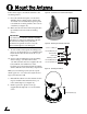
8 Mount the Antenna Follow these steps to mount the antenna to the mounting surface. Figure 19: “Forward” Arrow in Antenna Baseplate a. Place the antenna baseplate over the holes drilled in the mounting surface. Ensure the “Forward” arrow inside the baseplate points toward the bow and is parallel to the vessel’s centerline (see Figure 19). b. Make sure the four holes in the baseplate line up with the four holes in the mounting surface.
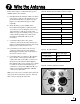
9 Wire the Switchplate Follow these steps to connect the switchplate to the antenna. Figure 22: Switchplate Wiring - Antenna Data Cable a. First dress the data and power cables from the antenna. Strip back the insulation of each wire approximately 1/4" (6 mm) and gently twist each wire to ensure a good electrical connection. b. Connect the data cable from the antenna to the terminal board on the back of the switchplate (see Figure 22). Be sure to match the wire colors with the terminal board label.
10 Wire the MCP and Receivers If you are installing a circular system, or a linear system for Sky Mexico, follow these steps to connect the switchplate to the MCP and the antenna to the receiver(s). Circular and Sky Mexico Systems Figure 24: MCP and Receiver Wiring a. Connect the main control cable (DB9-male to DB9-male) from the “Maintenance” port on the front or back of the switchplate to the “Antenna Unit” connector on the MCP (see Figure 24).
10 Wire the MCP and Receivers If you are installing a linear system (with the exception of Sky Mexico), follow these steps to connect the switchplate to the MCP and the antenna to the receiver(s). a. Connect the main control cable (DB9-male to DB9-male) from the “Maintenance” port on the front or back of the switchplate to the “Antenna Unit” connector on the MCP (see Figure 25).
11 Connect Power Follow these steps to connect power. The switchplate supplies power to both the antenna and the MCP. Figure 26: MCP Power Plug Terminal Screw (x2) a. Before you begin, disconnect vessel power. CAUTION For your own safety, disconnect vessel power and make sure the circuit is dead before you connect any power wires. b. Route a set of power wires from the switchplate’s power output terminals to the MCP (for cable specifications, see Figure 2 on page 3).
12 Mount the Switchplate & MCP In Step 4, you prepared the mounting sites for the switchplate and MCP. Now follow these steps to mount them. Figure 29: Mounting the Switchplate ting Moun ce Surfa Switchplate hplate Switc NOTE: As an alternative, the switchplate includes two additional mounting holes for installing within an electrical panel. If you chose this option, simply use two of the #6 screws to mount the switchplate to the panel. a.
13 Turn On the System Follow these steps to turn on the TracVision system. a. Ensure the antenna has a clear, unobstructed view of the sky so it can receive satellite signals. b. Apply power to the satellite TV receiver(s) and TV(s). c. Set the switchplate’s power switch to the “on” position to apply power to the TracVision system (see Figure 32). d. Wait one minute for system startup. When the MCP display shows “Set up satellite(s),” proceed to the next step.
14 Choose an Operating Mode If you are installing a circular system, choose the appropriate operating mode for your customer’s satellite TV service provider and satellite preferences (see Figure 33). You will select this mode in the next step.
15 Select Satellites Follow these steps and refer to the flowchart in Figure 35 to set up the system for a DIRECTV mode (see Step 14 on page 17 for a description of each mode). a. At “Set up satellite(s),” press the YES button on the MCP’s front panel. Circular Systems - DIRECTV Figure 35: DIRECTV Satellite Selection Menus on MCP Set up satellite(s)? Yes No b. At “Circular or Linear?,” press CIR. c. At “Service=DIRECTV,” press YES. d.
15 Select Satellites Follow these steps and refer to the flowchart in Figure 36 to set up the system for a DISH Network mode (see Step 14 on page 17 for a description of each mode). a. At “Set up satellite(s),” press the YES button on the MCP’s front panel. Circular Systems - DISH Network Figure 36: DISH Satellite Selection Menus on MCP Set up satellite(s)? Yes No b. At “Circular or Linear?,” press CIR. c. At “Service=DIRECTV,” press NEXT until the display shows “Service=DISH.” Then press YES.
15 Select Satellites Follow these steps and refer to the flowchart in Figure 37 to set up the system for ExpressVu. The antenna will track ExpressVu’s 91 and 82 satellites. a. At “Set up satellite(s),” press the YES button on the MCP’s front panel. Circular Systems - ExpressVu Figure 37: ExpressVu Satellite Selection Menus on MCP Set up satellite(s)? Yes No b. At “Circular or Linear?,” press CIR. c. At “Service=DIRECTV,” press NEXT until the display shows “Service=ExpressVu.” Then press YES. d.
15 Select Satellites Follow these steps and refer to the flowchart in Figure 38 to set up the system for a custom pair of satellites from the antenna’s library. a. At “Set up satellite(s),” press the YES button on the MCP’s front panel. Circular Systems - Custom Pair Figure 38: Custom Pair Satellite Selection Menus on MCP Set up satellite(s)? Yes No b. At “Circular or Linear,” press CIR. c. At “Service=DIRECTV,” press NEXT until the display shows “Service=Custom.” Then press YES. d.
15 Select Satellites Follow these steps and refer to the flowchart in Figure 39 to set up the system for one of the following European Trisat groups: Group Satellites Sat. B Sat. C Europe WB HotbirdWB Astra1 Astra2S Europe Hotbird Astra1 Astra2S HotbirdWB Figure 39: European Trisat Group Selection Menus on MCP Set up satellite(s)? Yes No Sat. A Scandinavia Linear Systems - Tri-Sat Group Sirius Thor a. At “Set up satellite(s),” press the YES button on the MCP’s front panel.
15 Select Satellites Follow these steps and refer to the flowchart in Figure 40 to set up the system for a custom pair of satellites from the antenna’s library. a. At “Set up satellite(s),” press the YES button on the MCP’s front panel. Linear Systems - Custom Pair Figure 40: Custom Pair Satellite Selection Menus on MCP Set up satellite(s)? Yes No b. At “Circular or Linear,” press LIN. c. At “Trisat Mode?,” press NO. d.
16 Set the LNB Skew Angle Follow these steps to set the antenna’s linear LNB to the skew angle you noted earlier. Linear Systems Only Figure 41: LNB Location on Back of Antenna’s Reflector a. Turn off and unplug the receiver(s). b. Disconnect antenna power at the switchplate. Reflector LNB CAUTION Disconnect power from the antenna and the receivers before you adjust the LNB. The antenna’s moving parts can cause injury. c. Remove the antenna’s radome, if you reinstalled it earlier in Step 8e.
17 Run a Check Switch Test If you set up the system for DISH Network or ExpressVu, follow these steps to run the receiver’s Check Switch test to configure the receiver for the desired satellites. IMPORTANT! This procedure must be performed while the vessel is docked in calm water. NOTE: If you are connecting multiple receivers, repeat this process for each additional receiver. You will need to connect each receiver, one at a time, to the “RF1” cable and perform the steps below.
18 Educate the Customer The installation process is complete! Before you leave the vessel, test the system to verify the antenna works properly. Then give the Customer Welcome Kit to the customer and explain how to use the system. Also be sure the customer understands the following: • Figure 45: Example of Satellite Blockage Keep the radome installed on the antenna at all times. The radome protects the antenna’s moving parts from wind, rain, and debris.
Appendices This section provides supplemental instructions for wiring multiple receivers. It also provides a list of available satellites, a system wiring diagram, and mounting templates for the belowdecks equipment. Contents A. Wiring 3+ Receivers ..........................29 B. Satellite Library..................................31 C. Position Grids.....................................32 D. Basic System Wiring Diagram .........33 Switchplate Mounting Template ...........35 MCP Flush Mounting Template ....
A Wiring 3+ Receivers To connect three or more receivers to a circular system, follow these steps to install an Eagle Aspen multiswitch (KVH part #72-0310) between the grounding block and the receivers, as shown in Figure 46. Circular Systems Figure 46: Multiswitch Wiring - Antenna with Circular Dual LNB 1. Connect an RF cable from the “RF1” connector on the grounding block to the “13V” connector on the multiswitch. 2.
A Wiring 3+ Receivers To connect three or more receivers to a system configured for Sky Mexico, follow these steps to install a Spaun model SMS 5602 NF multiswitch (KVH part #19-0413) between the grounding block and the receivers, as shown in Figure 47. Figure 47: Multiswitch Wiring - Sky Mexico 1. Connect an RF cable from the “RF1” connector on the grounding block to the “H/High” (Horizontal High) connector on the multiswitch. 2.
B Satellite Library The TracVision antenna can track a variety of DVB-compatible and DSS (DIRECTV) satellites. Most popular satellites are programmed in the antenna’s library (see the tables below). North America Europe Circular LNB Required Linear LNB Required Satellite, Longitude Name in Library Satellite, Longitude Name in Library DIRECTV, 72°W DSS_72 Astra 1, 19.2°E ASTRA1 DIRECTV, 101°W DSS_101 Astra 2N, 28.2°E ASTRA2N DIRECTV, 110°W* DSS_110 Astra 2S, 28.
C Position Grids If the vessel is located in Europe or North America, you may use the appropriate grid and table below to determine your approximate latitude and longitude.
D Basic System Wiring Diagram Circular and Sky Mexico Systems This wiring diagram shows a basic circular or Sky Mexico system configuration.
D Basic System Wiring Diagram Linear Systems This wiring diagram shows a basic linear system configuration.
.16" (4 mm) 2.36" (60 mm) 3.19" (81 mm) Panel Cutout 3.82" (97 mm) .32" (8 mm) (2.25 mm) 2.
.63" (16 mm) 3.08" (78 mm) 1.83" (46 mm) .63" (16 mm) 4x .136" (3.45 mm) 4x R .63" (16 mm) 7.62" (194 mm) 8.
KVH Industries, Inc. 50 Enterprise Center Middletown, RI 02842-5279 U.S.A. Phone: +1 401 847-3327 Fax: +1 401 849-0045 E-mail: info@kvh.com Internet: www.kvh.com © Copyright 2006 KVH Industries Inc. KVH Europe A/S Kokkedal Industripark 2B 2980 Kokkedal Denmark Phone: +45 45 160 180 Fax: +45 45 160 181 E-mail: info@kvh.dk Internet: www.kvh.com KVH and TracVision are registered trademarks of KVH Industries Inc.